Netgear WNR834Bv2 WNR834Bv2 Setup Manual - Page 7
Hardware Features, Front Panel, Back Panel - software
 |
View all Netgear WNR834Bv2 manuals
Add to My Manuals
Save this manual to your list of manuals |
Page 7 highlights
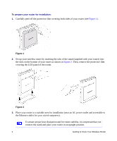
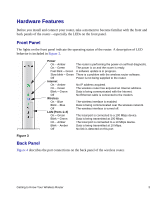
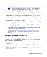
Hardware Features Before you install and connect your router, take a moment to become familiar with the front and back panels of the router-especially the LEDs on the front panel. Front Panel The lights on the front panel indicate the operating status of the router. A description of LED behavior is included in Figure 3. Figure 3 Power On - Amber The router is performing the power-on self-test diagnostic. On - Green The power is on and the router is ready. Fast blink - Green A software update is in progress. Slow blink - Green There is a problem with the wireless router software. Off Power is not being supplied to the router. Internet On - Amber No IP address acquired. On - Green The wireless router has acquired an Internet address. Blink - Green Data is being communicated with the Internet. Off No Ethernet cable is connected to the modem. Wireless On - Blue The wireless interface is enabled. Blink - Blue Data is being communicated over the wireless network. Off The wireless interface is turned off. LAN (Ports 1-4) On - Green The local port is connected to a 100 Mbps device. Blink - Green Data is being transmitted at 100 Mbps. On - Amber The local port is connected to a 10 Mbps device. Blink - Amber Data is being transmitted at 10 Mbps. Off No link is detected on this port. Back Panel Figure 4 describes the port connections on the back panel of the wireless router. Getting to Know Your Wireless Router 3
-
 1
1 -
 2
2 -
 3
3 -
 4
4 -
 5
5 -
 6
6 -
 7
7 -
 8
8 -
 9
9 -
 10
10 -
 11
11 -
 12
12 -
13
-
14
-
15
-
16
-
17
-
18
-
19
-
20
-
21
-
22
-
23
-
24
-
25
-
26
-
27
-
28
-
29
-
30
-
31
-
32
-
33
-
34
-
35
-
36
-
37
-
38
-
39
-
40
-
41
-
42
-
43
-
44
-
45
-
46
 |
 |
