NordicTrack Vgr 940 Uk Manual - Page 8
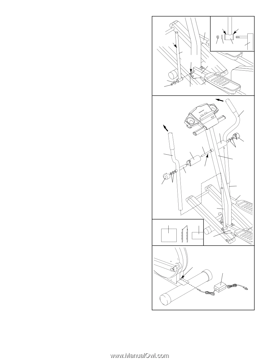
Apply grease to the Arm Axle 19. Insert the Arm Axle - power supply
 |
View all NordicTrack Vgr 940 manuals
Add to My Manuals
Save this manual to your list of manuals |
Page 8 highlights
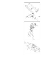
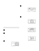
9. Apply grease to the welded bolt on the Left Pedal Arm (3). Slide a Chrome Tube (21) and a Chrome Tube Washer (84) onto the welded bolt. Make sure that the Chrome Tube is turned exactly as shown in the inset drawing. Then, tighten an M10 Nylon Locknut (26) onto the welded bolt. Attach the other Chrome Tube (not shown) to the Right Pedal Arm (4) in the same way. Apply a small amount of the included Teflon® lubricant to a paper towel. Rub a thin film of the lubricant onto both Chrome Tubes (21). 10. Slide the Left Upper Body Arm (7), which is marked with an "L" sticker, onto the Chrome Tube (21) on the Left Pedal Arm (3). Slide the Right Upper Body Arm (75) onto the Chrome Tube on the Right Pedal Arm (4). Make sure that the Upper Body Arms are on the correct sides-the upper ends should bend in the direction shown by the arrows. Next, slide an Axle Cover (74) onto the post on each Upper Body Arm. Apply grease to the Arm Axle (19). Insert the Arm Axle into the Upright (2), the right Axle Cover (74), and the Right Upper Body Arm (75) as shown. Push the Arm Axle into the Upright until the left end of the Axle is flush with the left side of the Upright. Next, raise the Left Upper Body Arm (7) and insert the Arm Axle into the left Axle Cover (74) and the Left Upper Body Arm. Centre the Arm Axle. Using the included push nut tool, tap two Push Nuts (15) about 3 mm (1/8 in.) onto each end of the Arm Axle (19). Make sure that the Push Nuts are turned as shown in the inset drawing. Note: It may be helpful if another person holds a block of wood against one end of the Arm Axle whilst you tap Push Nuts onto the other end. Press the two Pivot Axle Caps (34) onto the Arm Axle (19). 11. Plug the Power Supply (78) into the jack at the rear of the elliptical crosstrainer. Note: Your Power Supply may look different from the one pictured. 9 Lubricate Wide Side 4 Narrow Side 21 Grease 26 84 21 3 3 84 26 Welded Bolt 10 75 7 34 15 74 19 74 Grease Post 34 15 2 21 4 21 Push Nut Tool 15 19 3 11 Jack 78 12. Make sure that all parts of the elliptical crosstrainer are properly tightened. Note: Some hardware may be left over after assembly is completed. To protect the floor or carpet from damage, place a mat under the elliptical crosstrainer. 8
-
 1
1 -
2
-
 3
3 -
 4
4 -
 5
5 -
 6
6 -
 7
7 -
 8
8 -
 9
9 -
 10
10 -
 11
11 -
 12
12 -
 13
13 -
14
-
15
-
16
-
17
-
18
-
19
-
20
 |
 |