Oki C610dtn C610, C711 User's Guide (English) - Page 79
Holding the complete assembly by its top center, lower it into, place in the printer
 |
View all Oki C610dtn manuals
Add to My Manuals
Save this manual to your list of manuals |
Page 79 highlights
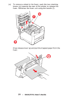
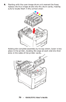
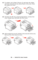
8. Starting with the cyan image drum unit nearest the fuser, replace the four image drums into the drum cavity, making sure to locate them in the correct order. Holding the complete assembly by its top center, lower it into place in the printer, locating the pegs at each end into their slots in the sides of the printer cavity. 79 - C610/C711 User's Guide
-
 1
1 -
2
-
3
-
4
-
5
-
6
-
7
-
8
-
9
-
10
-
11
-
12
-
13
-
14
-
15
-
16
-
17
-
18
-
19
-
20
-
21
-
22
-
23
-
24
-
25
-
26
-
27
-
28
-
29
-
30
-
31
-
32
-
33
-
34
-
35
-
36
-
37
-
38
-
39
-
40
-
41
-
42
-
43
-
44
-
45
-
46
-
47
-
48
-
49
-
50
-
51
-
52
-
53
-
54
-
55
-
56
-
57
-
58
-
59
-
60
-
61
-
62
-
63
-
64
-
65
-
66
-
67
-
68
-
69
-
70
-
71
-
72
-
73
-
 74
74 -
 75
75 -
 76
76 -
 77
77 -
 78
78 -
 79
79 -
 80
80 -
 81
81 -
 82
82 -
 83
83 -
 84
84 -
85
-
86
-
87
-
88
-
89
-
90
-
91
-
92
-
93
-
94
-
95
-
96
-
97
-
98
-
99
-
100
-
101
-
102
-
103
-
104
-
105
-
106
-
107
-
108
-
109
 |
 |

79
– C610/C711 User’s Guide
8.
Starting with the cyan image drum unit nearest the fuser,
replace the four image drums into the drum cavity, making
sure to locate them in the correct order.
Holding the complete assembly by its top center, lower it into
place in the printer, locating the pegs at each end into their
slots in the sides of the printer cavity.