Oki GL408e GL408e/GL412e Rewinder Install Guide - Page 10
Mounting the printer above the rewinder
 |
View all Oki GL408e manuals
Add to My Manuals
Save this manual to your list of manuals |
Page 10 highlights
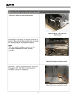
1) Mounting the printer above the rewinder A total of seven screws (cross recessed hexagonal bolt M4x10) are used to install the internal rewinder-dispenser to the printer chassis (Do not damage the PCB when using any tool such as screwdriver) Do not tighten all seven screws until you are sure the installation alignment is correct. Also check that all connectors have been reconnected. Two screws removed originally from the front of the printer, will be left unused. Next, we will reinstall the front cover of the internal rewinder-dispenser. First, connect the internal rewinder's cable to the connector at the front of the printer, as shown here. Make sure it is not compressed in any way when the front cover of the internal rewinder is mounted next. Reinstall the front cover of the internal rewinder and and temporarily tighten the two screws (bind screw M4×4) used to secure each side of the front cover. Figure 2d. Printer mounted on top of the internal rewinder コCネoクnタnーector Figure 2e. Connecting the internal rewinder signal cable Four screws to be secured in total Figure 2f. Mounting the front cover 10
-
 1
1 -
2
-
3
-
4
-
 5
5 -
 6
6 -
 7
7 -
 8
8 -
 9
9 -
 10
10 -
 11
11 -
 12
12 -
 13
13
 |
 |
