Panasonic AW-UE4 Basic Operating Instructions - Page 17
When using the WV-Q105A (optional accessory)
 |
View all Panasonic AW-UE4 manuals
Add to My Manuals
Save this manual to your list of manuals |
Page 17 highlights
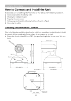
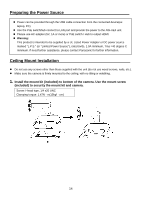
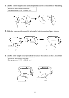
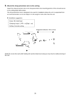
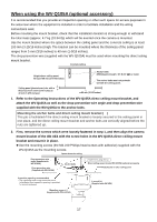
When using the WV-Q105A (optional accessory) It is recommended that you provide an inspection opening or other such space for access purposes in the area near where the equipment is installed in order to facilitate installation and the wiring connections work. Before mounting the mount bracket, check that the installation location is strong enough to withstand the total mass (approx. 4.7 kg (10.34 lb)) which will be exerted once the camera is mounted. Use the mount bracket where the space between the ceiling panel and the concrete ceiling is at least 100 mm (3-15/16 inches) high. The bracket can be mounted where the thickness of the ceiling panel ranges from 5 mm (3/16 inches) to 40 mm (1-9/16 inches). The drop-prevention wire (supplied with the WV-Q105A) must be used when mounting the direct ceiling mount bracket. 1. Refer to the Operating Instructions of the WV-Q105A direct ceiling mount bracket, and attach the WV-Q105A as well as the drop-prevention wire angle and drop-prevention wire supplied with the WV-Q105A to the anchor bolts. Mounting the anchor bolts and direct ceiling mount bracket ( ) This job is facilitated if the direct ceiling mount bracket is loosely secured to the ceiling panel in one place, and the direct ceiling mount bracket and anchor bolts are vertically aligned before the nuts are tightened up. 2. First, remove the screws which were loosely fastened in step 1, and then align the camera mount bracket of the AW-UE4 with the screw holes in the WV-Q105A direct ceiling mount bracket and mount it in place. Use the mounting screws (the M4-L60 Phillips head screws with adhesive) supplied with the WV-Q105A as the mounting screws. 17
-
 1
1 -
2
-
3
-
4
-
5
-
6
-
7
-
8
-
9
-
10
-
11
-
 12
12 -
 13
13 -
 14
14 -
 15
15 -
 16
16 -
 17
17 -
 18
18 -
 19
19 -
 20
20 -
 21
21 -
 22
22 -
23
-
24
-
25
-
26
-
27
-
28
-
29
-
30
-
31
-
32
-
33
-
34
-
35
-
36
-
37
-
38
-
39
-
40
-
41
-
42
-
43
-
44
-
45
-
46
-
47
-
48
-
49
-
50
-
51
-
52
-
53
-
54
-
55
-
56
-
57
-
58
-
59
-
60
-
61
-
62
-
63
-
64
-
65
-
66
-
67
-
68
 |
 |
