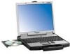
Panasonic CF-74ECBAXBM Service Manual - Page 27
Removing the Handle Ass'y, Removing the Bottom Case, Removing the Wireless Module and, MDC Module, 1
 |
UPC - 092281864044
View all Panasonic CF-74ECBAXBM manuals
Add to My Manuals
Save this manual to your list of manuals |
Page 27 highlights
10.1.7. Removing the Handle Ass'y Handle Cover R Sleeves B Handle Cover L 10.1.9. Removing the Wireless Module and MDC Module Wireless Module Antenna Cable (Black) Antenna Cable (Gray) Sleeves A Handle Ass'y Sleeves A MDC Module Modem Cable 1. Remove the two Screws . 2. Remove the three Screws , and remove the Handle Cover L and R. 3. Remove the two Sleeves A, Handle Ass'y and two Sleeves B. Screws : DRHM4+10FKS Screws : DRSB2+6FKL 10.1.8. Removing the Bottom Case 1. Remove the two Antenna Cables from the two Connectors. • Antenna Cable (Black): MAIN Connector • Antenna Cable (Gray): AUX Connector 2. Remove the two Screws . 3. Remove the Wireless Module. 4. Remove the two Screws . 5. Disconnect the Modem Cable from the Connector. 6. Remove the MDC Module. Screws : DFHE5025XA 10.1.10. Removing the Main PCB Main PCB CN6 CN21 CN802 CN18 CN15 Bottom Cover 1. Remove the six Screws . 2. Remove the ten Screws . 3. Remove the two Screws . 4. Open the Lid Rubbers and remove the Bottom Cover. Screws : DXSB2+6FNL Screws : DXYN2+J16FNL Screws : DXYN2+J8FNL CN7 CN24 CN26 CN28 CN19 MP Guide 10-3
-
 1
1 -
2
-
3
-
4
-
5
-
6
-
7
-
8
-
9
-
10
-
11
-
12
-
13
-
14
-
15
-
16
-
17
-
18
-
19
-
20
-
21
-
 22
22 -
 23
23 -
 24
24 -
 25
25 -
 26
26 -
 27
27 -
 28
28 -
 29
29 -
 30
30 -
 31
31 -
 32
32 -
33
-
34
-
35
-
36
-
37
-
38
-
39
-
40
-
41
-
42
-
43
-
44
-
45
-
46
-
47
-
48
-
49
-
50
-
51
-
52
-
53
-
54
-
55
-
56
-
57
-
58
-
59
-
60
-
61
-
62
-
63
-
64
-
65
-
66
-
67
-
68
-
69
-
70
-
71
-
72
-
73
-
74
-
75
-
76
-
77
-
78
-
79
-
80
-
81
-
82
-
83
 |
 |
