Panasonic DMR-EZ28K Dvd Recorder - English / Spanish - Page 61
Using an RF Modulator, Using an HDMI High Definition, Multimedia Interface Cable
 |
UPC - 037988256624
View all Panasonic DMR-EZ28K manuals
Add to My Manuals
Save this manual to your list of manuals |
Page 61 highlights
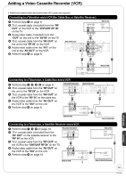
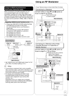
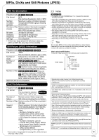
Using an RF Modulator Using an HDMI (High Definition Multimedia Interface) Cable When connected to an HDMI compatible unit, an uncompressed digital audio and video signal is transmitted, enabling you to enjoy high quality digital video and audio with just one cable. When connecting to an HDMI-compatible HDTV (High Definition Television), the output can be switched to 1080p, 1080i or 720p HD video. Regarding "HDAVI Control" function (➔ 34) • Please use HIGH SPEED HDMI cables that have the HDMI logo (as shown on the cover). It is recommended that you use Panasonic's HDMI cable. Recommended part number: RP-CDHG10 (1.0 m/3.3 ft.), RP-CDHG15 (1.5 m/4.9 ft.), RP-CDHG20 (2.0 m/6.6 ft.), RP-CDHG30 (3.0 m/9.8 ft.), RP-CDHG50 (5.0 m/16.4 ft.), etc. • Non-HDMI-compliant cables cannot be used. Rear of Amplifier or System Component HDMI IN HDMI OUT Rear of TV HDMI IN HDMI cable (not included) AV OUT OPTICAL DIGITAL AUDIO OUT O S VIDEO (PCM/BITSTREAM) Rear of this unit • Set "HDMI Priority" and "HDMI Audio Output" to "On" (➔ 54, 55). (The default setting is "On".) Notes • If connecting to equipment that is only compatible with 2 channels output, audio with 3 channels or more will be down-mixed (➔ 77) and output as 2 channels (some discs cannot be down-mixed). • For display units compatible with HDCP (High bandwidth Digital Content Protection) that are equipped with a digital DVI input terminal (PC monitors, etc.): Depending on the unit, images may not display properly or at all when connecting with a DVI/HDMI switching cable (audio cannot be output). • If your Television does not have Audio/Video Terminals. Connecting to a Television Connect cables in steps and (same as those on page 8) as follows. Cable from the wall or antenna signal Rear of this unit step 2 RF Modulator RF IN RF OUT Red White Yellow step 3 Red White Yellow AUDIO IN VIDEO R L IN Rear of TV VHF/UHF RF IN Connecting to a Television with a Video Cassette Recorder or a Cable Box or Satellite Receiver Connect cables in steps and (same as those on page 9 or 10) as follows. Cable from the wall or antenna signal (Video Cassette Recorder or Cable Box Only) Rear of this unit Red White Yellow Rear of Video Cassette Recorder or Cable Box or Satellite Receiver step step 3 2 RF OUT Red White Yellow RF Modulator RF IN RF OUT AUDIO IN VIDEO R L IN Rear of TV VHF/UHF RF IN Reference 61 RQT9046
-
 1
1 -
2
-
3
-
4
-
5
-
6
-
7
-
8
-
9
-
10
-
11
-
12
-
13
-
14
-
15
-
16
-
17
-
18
-
19
-
20
-
21
-
22
-
23
-
24
-
25
-
26
-
27
-
28
-
29
-
30
-
31
-
32
-
33
-
34
-
35
-
36
-
37
-
38
-
39
-
40
-
41
-
42
-
43
-
44
-
45
-
46
-
47
-
48
-
49
-
50
-
51
-
52
-
53
-
54
-
55
-
 56
56 -
 57
57 -
 58
58 -
 59
59 -
 60
60 -
 61
61 -
 62
62 -
 63
63 -
 64
64 -
 65
65 -
 66
66 -
67
-
68
-
69
-
70
-
71
-
72
-
73
-
74
-
75
-
76
-
77
-
78
-
79
-
80
-
81
-
82
-
83
-
84
 |
 |
