Panasonic PT-D3500 Dlp Projector - English/ French - Page 18
Connection, Setup Precautions - manual
 |
View all Panasonic PT-D3500 manuals
Add to My Manuals
Save this manual to your list of manuals |
Page 18 highlights
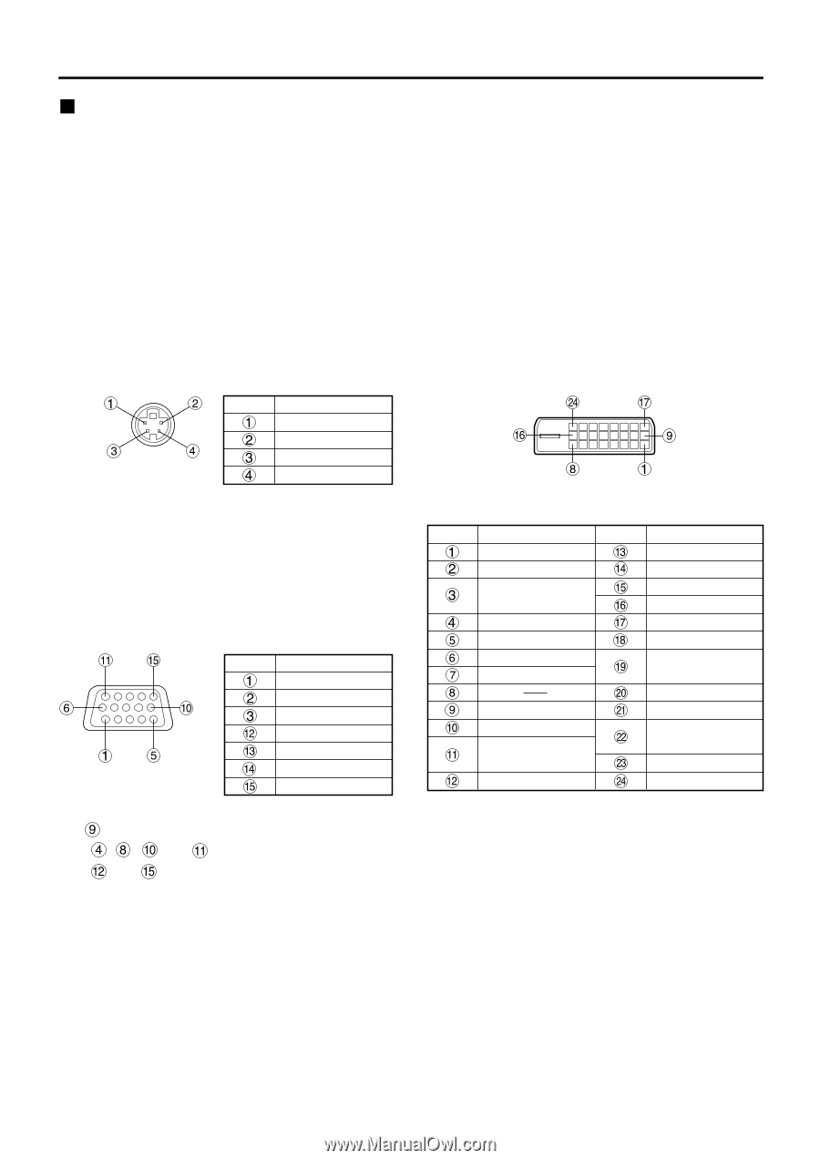
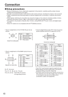
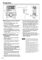
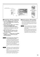
Connection Setup precautions • Before connecting any of your video/audio equipment to the projector, carefully read the owners manual supplied with the equipment once again. • All cable connections should be made with the entire system devices, including the projector, first turned off. • Obtain commercial interconnecting cables for devices supplied with no accessory or optional interconnect cables. • Video signals containing too much jitter may cause the images on the screen to randomly wobble or shake. Inserting a time base corrector (TBC) in the projector's video line will relieve this problem. • The projector only accepts composite-video, S-video, analog-RGB (with TTL sync. level), and digital signal from PC. • Some PC models are not compatible with the PT-D3500U projector. • The pin assignments on the S-VIDEO IN port are as follows: Pin No. Signal Ground (luminance) Ground (color) Luminance signal Viewed from mating side Color signal • The pin assignments on the RGB2 input port are as follows: Viewed from mating side Pin No. Signal R/PR G/G · SYNC/Y B/PB SDA HD/SYNC VD SCL Pin : Not used. Pins - , and : Ground. Pins and : Valid if the PC has the corresponding function. • The pin assignments on the DVI-D input port are as follows (interface with DVI-D output port on PC): Viewed from mating side Pin No. Signal T. M. D. S data 2- T. M. D. S data 2+ T. M. D. S data 2/4 shield T. M. D. S data 4- T. M. D. S data 4+ DDC clock DDC data T. M. D. S data 1T. M. D. S data 1+ T. M. D. S data 1/3 shield T. M. D. S data 3- Pin No. Signal T. M. D. S data 3+ +5 V Ground Hot plug sense T. M. D. S data 0- T. M. D. S data 0+ T. M. D. S data 0/5 shield T. M. D. S data 5- T. M. D. S data 5+ T. M. D. S clock shield T. M. D. S clock+ T. M. D. S clock- • The DVI-D input terminal supports single link only. • EDID settings should be performed to suit the DVI equipment being connected. (Page 34) • The DVI-D input terminal can be used to connect to a DVI equipment, but note that images may not appear or the projector may not work properly when connected to certain DVI equipment. 18
-
 1
1 -
2
-
3
-
4
-
5
-
6
-
7
-
8
-
9
-
10
-
11
-
12
-
 13
13 -
 14
14 -
 15
15 -
 16
16 -
 17
17 -
 18
18 -
 19
19 -
 20
20 -
 21
21 -
 22
22 -
 23
23 -
24
-
25
-
26
-
27
-
28
-
29
-
30
-
31
-
32
-
33
-
34
-
35
-
36
-
37
-
38
-
39
-
40
-
41
-
42
-
43
-
44
-
45
-
46
-
47
-
48
-
49
-
50
-
51
-
52
-
53
-
54
-
55
-
56
-
57
-
58
-
59
-
60
-
61
-
62
-
63
-
64
-
65
-
66
-
67
-
68
-
69
-
70
-
71
-
72
 |
 |