Panasonic PT-D3500 Dlp Projector - English/ French - Page 41
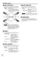
Using The Remote 2 Terminal
 |
View all Panasonic PT-D3500 manuals
Add to My Manuals
Save this manual to your list of manuals |
Page 41 highlights
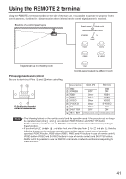
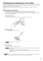
;Using the;REMOTE 2 terminal Using the REMOTE 2 terminal provided on the side of the main unit, it is possible to operate the projector from a control panel etc. furnished in a distant location where infrared remote control signal cannot be received. Example of a control panel layout Remote terminal External control Remote terminal/External control STANDBY ON LAMP RGB1 VIDEO RGB2 S-VIDEO Projector set up in a meeting room DVI Control panel located in a different room Pin assignments and control Be sure to short-circuit Pins and when controlling. D-Sub 9-pin (female) external appearance Names of terminals Open (H) Short (L) GND POWER RGB1 RGB2 VIDEO S-VIDEO DVI SHUTTER RST / SET GND OFF ON Other RGB1 Other RGB2 Other VIDEO Other S-VIDEO Other DVI OFF ON Controlled by remote control Controlled by external contact Note • The following buttons on the remote control and the operation area of the projector can no longer be operated when pins and are shorted: POWER button and SHUTTER button. Neither will it be possible to use the RS232C commands or network functions corresponding to these functions. • If you short pin and pin , and also short one of the pins from to and pin , then the following buttons on the projector operating area and the remote control can no longer be operated: POWER button, RGB button (RGB1, RGB2 and DVI buttons in case of remote control), VIDEO button (VIDEO and S-VIDEO buttons in case of remote control) and SHUTTER button. Neither will it be possible to use the RS232C commands or network functions corresponding to these functions. 41
-
 1
1 -
2
-
3
-
4
-
5
-
6
-
7
-
8
-
9
-
10
-
11
-
12
-
13
-
14
-
15
-
16
-
17
-
18
-
19
-
20
-
21
-
22
-
23
-
24
-
25
-
26
-
27
-
28
-
29
-
30
-
31
-
32
-
33
-
34
-
35
-
 36
36 -
 37
37 -
 38
38 -
 39
39 -
 40
40 -
 41
41 -
 42
42 -
 43
43 -
 44
44 -
 45
45 -
 46
46 -
47
-
48
-
49
-
50
-
51
-
52
-
53
-
54
-
55
-
56
-
57
-
58
-
59
-
60
-
61
-
62
-
63
-
64
-
65
-
66
-
67
-
68
-
69
-
70
-
71
-
72
 |
 |
