Panasonic PT60DL54J PT50DL54 User Guide - Page 10
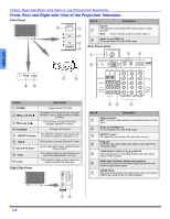
Front, Rear And Right Side View Of The Projection Television
 |
View all Panasonic PT60DL54J manuals
Add to My Manuals
Save this manual to your list of manuals |
Page 10 highlights
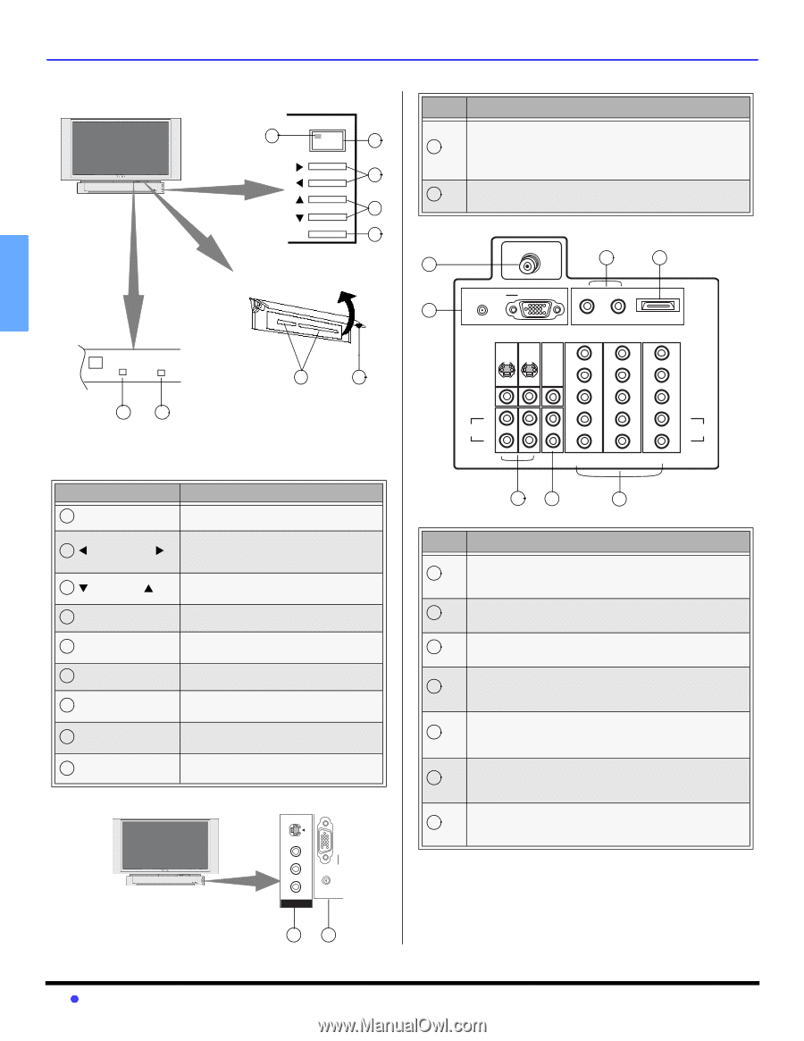
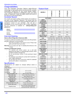
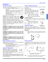
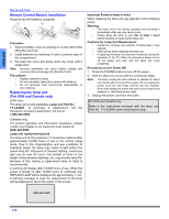
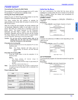
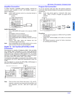
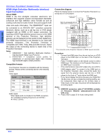
ENGLISH FRONT, REAR AND RIGHT SIDE VIEW OF THE PROJECTION TELEVISION Front, Rear and Right side View of the Projection Television Front Panel Item # Description POWER 5 1 Input 3 A/V inputs for connecting VCR, Palmcorders or other 1 devices. VOL 2 CH 3 Note: Press TV/Video button to select Video 3. 2 Audio In and RGB 2 In For connecting a PC with RGB output. TV/VIDEO 4 Rear Panel Jacks ANT 1 7 6 Temp Lamp 8 9 Open 7 6 Feature Description 1 POWER Toggles power OFF/ON 2 WVOL and VOLX 3 TCH and CHS Decrease or increase volume, navigate left/right in menu, adjust selected feature in menu. Tune to lower or higher channels, navigate up/down in menus. 4 TV/VIDEO 5 ON/OFF Indicator Change input source The ON/OFF indicator LED (green) will be lit when Projection Television is on. 6 DOOR 7 SD and PC Slots 8 Temp 9 Lamp Pull up here to access SD and PC slots. Use to insert and remove cards for Photo Viewer feature. This indicator lights up when there is an abnormal temperature in the unit. This indicator lights up when there is a malfunction with the lamp unit. Right Side Panel S-VIDEO RGB2 IN AUDIO IN T VIDEO L AUDIO R INPUT3 AUDIO IN RGB 1 IN R-AUDIO IN-L 2 HDMI AV IN IN 1 IN 2 OUT IN 1 IN 2 IN 3 Y Y Y S-VIDEO PB PB PB VIDEO VIDEO PR PR PR L AUDIO R L L L L AUDIO R R R R COMPONENT VIDEO INPUT 3 4 5 Item # Description Antenna Inputs 1 ANT - Connect cable antenna or terrestrial antenna to this input. 2 Audio In and RGB 1 In For connecting a PC with RGB output. 3 INPUTS 1 and 2 A/V inputs for connecting VCR and other devices. Prog Out 4 Terminals that output fixed and variable audio and NTSC composite video. COMPONENT VIDEO (Y-PB-PR) INPUTS 5 Use these jacks for connecting devices such as a DVD player or Set Top Box. HDMI (High Definition Multimedia Interface) 6 Input that accepts uncompressed digital signal and multi channel digital audio signal. AUDIO IN R/L 7 Use these audio inputs when DVI devices are connected to HDMI input using the DVI to HDMI adaptor. 1 2 8z
-
 1
1 -
2
-
3
-
4
-
 5
5 -
 6
6 -
 7
7 -
 8
8 -
 9
9 -
 10
10 -
 11
11 -
 12
12 -
 13
13 -
 14
14 -
 15
15 -
16
-
17
-
18
-
19
-
20
-
21
-
22
-
23
-
24
-
25
-
26
-
27
-
28
-
29
-
30
-
31
-
32
-
33
-
34
-
35
-
36
-
37
-
38
-
39
-
40
-
41
-
42
-
43
-
44
-
45
-
46
-
47
-
48
-
49
-
50
-
51
-
52
-
53
-
54
-
55
-
56
-
57
-
58
-
59
-
60
-
61
-
62
-
63
-
64
-
65
-
66
-
67
-
68
-
69
-
70
-
71
-
72
-
73
-
74
-
75
-
76
-
77
-
78
-
79
-
80
-
81
-
82
-
83
-
84
-
85
-
86
-
87
-
88
-
89
-
90
-
91
-
92
-
93
-
94
-
95
-
96
-
97
-
98
-
99
-
100
-
101
-
102
-
103
-
104
-
105
-
106
-
107
-
108
-
109
-
110
-
111
-
112
 |
 |