Panasonic PVGS34PKG Digital Video Camera - Page 11
POWER SUPPLY, Using the, AC Adaptor
 |
View all Panasonic PVGS34PKG manuals
Add to My Manuals
Save this manual to your list of manuals |
Page 11 highlights
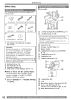
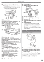
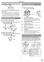
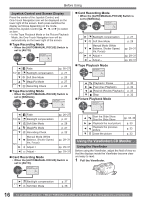
Before Using 15 Audio-Video Output Jack [AV OUT] (pp. 36, 37) • Connecting an AV Cable to this jack activates the Camcorder's built-in speaker. • When connecting the pin plug of the AV Cable to this jack, plug it in as far as it goes. 16 17 20 18 19 16 Cassette Holder 17 Cassette Compartment Cover (pp. 13~14) 18 USB Jack [ ] (pp. 40, 41, 43) 19 DV Input/Output Terminal (pp. 37, 38) • Connect this to the digital video equipment. 20 Built-in LED Light (p. 24) 22 23 24 25 26 30 21 27 31 32 28 33 29 32 Mode Dial (p. 15) 33 Joystick Control (pp. 15~16, 17~18) 34 35 36 38 37 34 Shoulder Strap Holders (p. 13) 35 Reset Button [RESET] (pp. 59, 61, 62) 36 Grip Belt (p. 13) 37 Battery Eject Switch [BATTERY RELEASE] (p. 12) 38 Tripod Receptacle • This is a hole for attaching the Camcorder to optional tripod. (Please carefully read the Operating Instructions for how to attach the tripod to the Camcorder.) • You cannot open the Card Slot Cover when the tripod is used. Insert the card first and then attach the tripod. Power Supply Using the AC Adaptor 21 Viewfinder (pp. 16~17, 59) Due to limitations in LCD production technology, there may be some tiny bright or dark spots on the Viewfinder screen. However, this is not a malfunction and does not affect the recorded picture. 22 Eyepiece Corrector Knob (p. 17) 23 Photoshot Button [PHOTO SHOT] (pp. 22, 23) 24 Mode Selector Switch [AUTO/MANUAL/FOCUS] (pp. 22, 28~31) 25 Cassette Eject Lever [OPEN/EJECT] (p. 13) 26 Power Switch [OFF/ON] (pp. 15, 22) 27 Quick Start Recording Button [QUICK START] (p. 25) Quick Start Recording Lamp (p. 25) 28 Menu Button [MENU] (p. 17) 29 Recording Start/Stop Button (p. 22) 30 Power Lamp [POWER] (p. 15) 31 Light Button [LIGHT] (p. 24) 1 Connect the DC Cable to the Camcorder. 2 Connect the DC Cable to the AC Adaptor. 3 Connect the AC Cable to the AC Adaptor and the AC Jack. • Before connecting or disconnecting the power supply, set the [OFF/ON] Switch 26 on the Camcorder to [OFF] and make sure that [POWER] Lamp 30 is not lit. (p. 15) 11
-
 1
1 -
2
-
3
-
4
-
5
-
 6
6 -
 7
7 -
 8
8 -
 9
9 -
 10
10 -
 11
11 -
 12
12 -
 13
13 -
 14
14 -
 15
15 -
 16
16 -
17
-
18
-
19
-
20
-
21
-
22
-
23
-
24
-
25
-
26
-
27
-
28
-
29
-
30
-
31
-
32
-
33
-
34
-
35
-
36
-
37
-
38
-
39
-
40
-
41
-
42
-
43
-
44
-
45
-
46
-
47
-
48
-
49
-
50
-
51
-
52
-
53
-
54
-
55
-
56
-
57
-
58
-
59
-
60
-
61
-
62
-
63
-
64
-
65
-
66
-
67
-
68
-
69
-
70
-
71
-
72
 |
 |
