Panasonic WV-CF294T Color Cctv Camera-english/french - Page 12
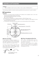
DISASSEMBLING THE CAMERA, CONNECTIONS, To mount the camera directly on, the wall/ceiling
 |
UPC - 791871505175
View all Panasonic WV-CF294T manuals
Add to My Manuals
Save this manual to your list of manuals |
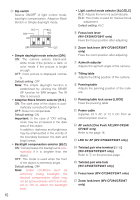
Page 12 highlights
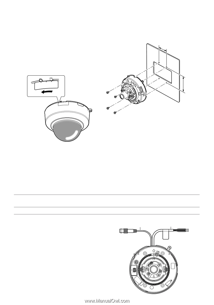
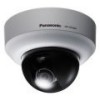
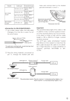
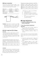
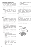
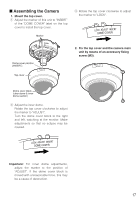
I Disassembling the Camera 1. Remove the top cover. • Adjust the marker of this unit to "INSERT" of the "DOME COVER" label on the top cover and turn the top cover counterclockwise to remove it. • The clear dome cover and the inner dome cover are joined into a single unit. Therefore, never try to remove them. mark four screw positions with a pen. 3. Mount the camera on the wall/ceiling with 4 screws (procured locally). 4. Fasten all the mounting screws. 46 mm {1-13/16"} LOCK ADJUST INSERT DOME COVER TOP LOOK 83.5 mm {3-5/16"} LOCK ADJUST INSERT DOME COVER Camera mounting screw x4 (not supplied) G To mount the camera directly on the wall/ceiling 1. Prepare the mounting space. 2. Place the camera on the wall/ceiling and G To mount the camera on a twogang junction box 1. Install the two-gang junction box on the wall/ceiling. 2. Mount the camera on the two-gang junction box with 4 screws (procured locally). 3. Fasten all the mounting screws. The mounting requirements are shown as follows. Mounting place Model Ceiling/wall (direct mounting) Recommended Number of screw screws M4 4 pcs. Minimum pullout strength 196 N {20 kgf} I Connections G Video output connection Connect the video output connector to the monitor or other system devices with the procured coaxial cable or LAN cable. The maximum extensible cable length is shown in the table. Video output connector Power cable TOP LOCK BLC ALC ELC B.S D/N ON OFF 12
-
 1
1 -
2
-
3
-
4
-
5
-
6
-
 7
7 -
 8
8 -
 9
9 -
 10
10 -
 11
11 -
 12
12 -
 13
13 -
 14
14 -
 15
15 -
 16
16 -
 17
17 -
18
-
19
-
20
-
21
-
22
-
23
-
24
-
25
-
26
-
27
-
28
-
29
-
30
-
31
-
32
-
33
-
34
-
35
-
36
-
37
-
38
-
39
-
40
 |
 |