Panasonic WV-CP500 Installation Guide - Page 19
Turn on the power.
 |
View all Panasonic WV-CP500 manuals
Add to My Manuals
Save this manual to your list of manuals |
Page 19 highlights
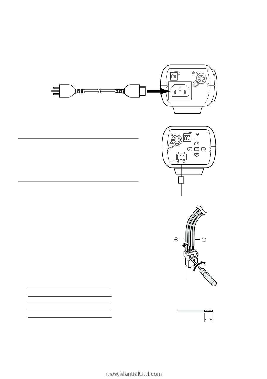
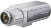
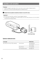
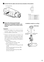
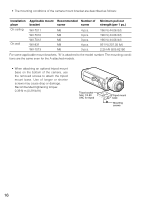
n Turn on the power. WV-CP500 The included power cord is connected to this power connector. Connect between the power connector on the rear side of the camera and a plug socket with the supplied power cord. 120 V AC 60 Hz Power cord (accessory) ALARM OUT POWER GND ALARM IN VIDEO OUT 120V ~ 60Hz WV-CP504 Important: • The power supply of 24 V AC/12 V DC shall be insulated against 120 V AC. • The power supply is automatically selected either 24 V AC or 12 V DC. No setting is required with this camera. q Loosen the screw of the power cord plug (accessory). w Connect the power supply (option) of 24 V AC or 12 V DC to the power cord plug. Strip the end of the wire by 3 mm to 7 mm {1/8" to 1/4"}, and twist the stripped part of the wire sufficiently to avoid short circuit. • Specification of cable (wire) AWG #16 - #28, Single core, twisted * Check whether the stripped part of the wire is not exposed and is securely connected. C B A ALARM OUT GND VIDEO OUT POWER ALARM IN NEAR 24V ~ IN 1-L 2-N GND (LEFT) (UP) BF/MENU FAR (SET) (RIGHT) (DOWN) 12V IN NC To 24 V AC/12 V DC power supply AC 24 V 2-N GND 1-L DC 12 V @ (GND) NC ! Power cord plug (accessory) Stripped e Tighten the screw of the power cord plug. r Connect the power cord plug to the AC/DC Approx. 3 mm - 7 mm {1/8" to 1/4"} power terminal on the rear side of the camera. * Make sure that the power cord plug is inserted fully into the AC/DC power supply terminal. 19
-
 1
1 -
2
-
3
-
4
-
5
-
6
-
7
-
8
-
9
-
10
-
11
-
12
-
13
-
 14
14 -
 15
15 -
 16
16 -
 17
17 -
 18
18 -
 19
19 -
 20
20 -
 21
21 -
 22
22 -
 23
23 -
 24
24 -
25
-
26
-
27
-
28
-
29
-
30
-
31
-
32
 |
 |