Panasonic WVSF336 WVSF332 User Guide - Page 21
bracket WV-Q105 PAL models only, Using the optional ceiling mount
 |
View all Panasonic WVSF336 manuals
Add to My Manuals
Save this manual to your list of manuals |
Page 21 highlights
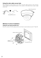
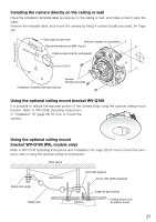
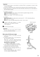
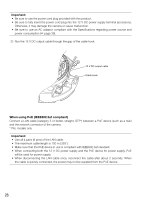
Installing the camera directly on the ceiling or wall Place the installation template label (accessory) on the ceiling or wall, and make a hole to pass the cable. Remove the template label, and mount the camera by fixing 4 screws (locally procured). (☞ Page 28 ) 40 mm {{114--691/3m1/6m1"6}"} Side cable access hole Direction marker for installation Recommended screw (M4: 4 pcs.) Cable access hole for ceiling/wall MONITOOURT 4 EXT 3 FTROOPNT 1 I/O 2 83.5 mm {3-5/16"} N 20 mm {13/16"} AOUUDTIO MLIINCE IN 1100B0BASA F Screws (locally procured) 12V=IN Installation template label (accessory) Using the optional ceiling mount bracket WV-Q168 It is possible to reduce the exposed portion of the camera body using the optional ceiling mount bracket. Refer to WV-Q168 Operating Instructions or "Installation" (☞ page 28) for how to mount the camera. Using the optional ceiling mount bracket WV-Q105 (PAL models only) Refer to WV-Q105 Operating Instructions and "Installation" (☞ page 28) for how to mount the camera in case of using the optional ceiling mount bracket. Roof space Safety wire angle Anchor bolt Safety wire WV-Q105 (option) (4 pcs, WV-Q105 supplied) Camera Cable tie (accessory) Ceiling board such as plaster board 21
-
 1
1 -
2
-
3
-
4
-
5
-
6
-
7
-
8
-
9
-
10
-
11
-
12
-
13
-
14
-
15
-
 16
16 -
 17
17 -
 18
18 -
 19
19 -
 20
20 -
 21
21 -
 22
22 -
 23
23 -
 24
24 -
 25
25 -
 26
26 -
27
-
28
-
29
-
30
-
31
-
32
-
33
-
34
-
35
-
36
-
37
-
38
-
39
-
40
-
41
-
42
-
43
-
44
 |
 |
