Panasonic WVSF336 WVSF332 User Guide - Page 23
Connection
 |
View all Panasonic WVSF336 manuals
Add to My Manuals
Save this manual to your list of manuals |
Page 23 highlights
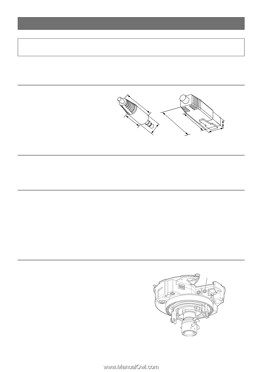
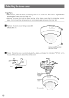
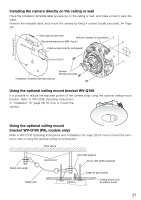
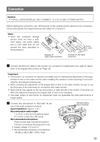
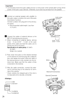
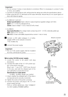
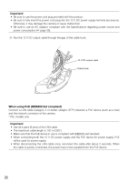
Connection Caution: • FOR UL LISTED MODEL(S), ONLY CONNECT 12 V DC CLASS 2 POWER SUPPLY. Before starting the connection, turn off the power of this camera and the devices to be connected. Check and prepare the required devices and cables for connection. Note: • Since the connector storage section does not have a sufficient space, use audio cables and a LAN cable that do not exceed the sizes described in the illustrations. 30 mm 17Smtramig{h2t1s/3e2c"ti}on {1-3/16"} 40 mm {13-09S/m1tr6ma"ig}{h1t-3s/e1c6t"io}n 9 mm {11/32"} 13 mm {1/2"} {1ø1/932m"}m Example of audio cable connector Example of LAN cable connector z Connect the RCA pin cable to the monitor out connector for adjustment (only used for adjust- ment of the angular field of view). (☞ Page 16) Important: • The monitor out connector for service is provided only for checking the adjustment of the angu- lar field of view on the video monitor when installing the camera or when servicing. It is not provided for recording/monitoring use. • When checking the adjustment of the angular field of view on the video monitor, be sure to use the RCA jack of the main body for connection with video monitor. • Black bands may appear at the top and bottom or right and left of the screen. (That does not affect the adjustment because the angular field of view is not changed.) • The video output on the monitor for adjustment does not guarantee the video performance or image quality. x Connect the microphone to MIC/LINE IN (for use of the audio reception function). Input impedance: Approx. 2 kΩ Recommended cable length: 1 m {3.3'} or less (for microphone input) 10 m {33'} or less (for LINE input) Recommended microphone: Plug-in power type microphone (option) Connect a monaural mini plug (ø3.5 mm). • Supply voltage: 2.5 V±0.5 V • Recommended sensitivity of microphone: -48 dB ±3 dB (0 dB=1 V/Pa,1 kHz) MONITO OU RT FTROOPNT 4 E3XT2I/O1 Microphone/line input connector AUODUITO MLICIN/ E IN 101B0A0SBEA-STE/-IX IN F 23
-
 1
1 -
2
-
3
-
4
-
5
-
6
-
7
-
8
-
9
-
10
-
11
-
12
-
13
-
14
-
15
-
16
-
17
-
 18
18 -
 19
19 -
 20
20 -
 21
21 -
 22
22 -
 23
23 -
 24
24 -
 25
25 -
 26
26 -
 27
27 -
 28
28 -
29
-
30
-
31
-
32
-
33
-
34
-
35
-
36
-
37
-
38
-
39
-
40
-
41
-
42
-
43
-
44
 |
 |