Panasonic WVSF336 WVSF332 User Guide - Page 28
Installation, Camera mounting
 |
View all Panasonic WVSF336 manuals
Add to My Manuals
Save this manual to your list of manuals |
Page 28 highlights
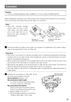
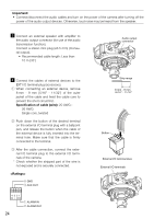
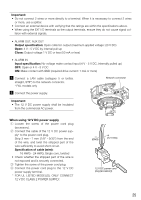
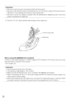
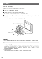
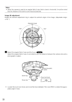
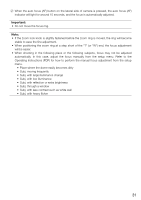
Installation Camera mounting Installation shall be conducted after turning off each device. z Detach the dome cover. (☞ Page 18) x Connect the cables to the camera. (☞ Pages 23 to 27) As necessary, use a cable tie (accessory) to assemble the cables. c Mount the camera. (The illustration represents the case in which a two-gang junction box is installed.) • Fix the camera with 4 screws (M4, locally procured) Direction marker for installation MONITOOURT 4 FTROOPNT EXT 3 I/O 2 1 Screws (locally procured) F N AOUUDTIO MLINICE IN 1100B0BAAS Two-gang junction box 12V=IN Important: • When tightening the screws, be careful to ensure that the cables does not tangle the cables. Note: • For ceiling mounting "gFRONT" of direction marker for installation indicates the center of panning. Adjustment of lens direction will become easier when the camera is mounted with the "gFRONT" marker oriented to the desired shooting area. Refer to the "Adjustment" section (☞ pages 29 to 33) for further information about adjustment. • For wall mounting The camera shall be mounted with the "gFRONT" marker facing upward. 28
-
 1
1 -
2
-
3
-
4
-
5
-
6
-
7
-
8
-
9
-
10
-
11
-
12
-
13
-
14
-
15
-
16
-
17
-
18
-
19
-
20
-
21
-
22
-
 23
23 -
 24
24 -
 25
25 -
 26
26 -
 27
27 -
 28
28 -
 29
29 -
 30
30 -
 31
31 -
 32
32 -
 33
33 -
34
-
35
-
36
-
37
-
38
-
39
-
40
-
41
-
42
-
43
-
44
 |
 |
