Panasonic WVSF336 WVSF332 User Guide - Page 29
Adjustment
 |
View all Panasonic WVSF336 manuals
Add to My Manuals
Save this manual to your list of manuals |
Page 29 highlights
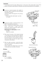
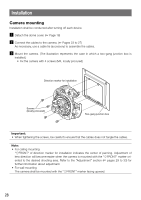
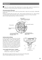
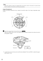
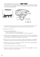
Adjustment z Adjust the camera angle. When determining the camera angle, repeat fine adjustments by gradually moving the panning table, tilting table, and azimuth adjustment ring. Horizontal position (Panning) Loosen the panning lock screw, rotate the panning table to adjust the pan direction. (Adjustable range: 350 °) Panning is possible within the range of 180 ° (when panning clockwise) and 170 ° (when panning counterclockwise). After adjustment, tighten the panning lock screw to fix the panning table. (Recommended tightening torque: 0.39 N.m {0.29 lbf·ft}) Home position * The position where the home position markers are aligned Panning table MONITOR OUT Panning lock screw [LOCK] LOCK Counterclockwise panning end maker: (Rotation within the range of 170 °) EXT FRONT TOP Home position markers K TOP BASE-T/ BASE TX 12V=IN Clockwise panning end marker: (Rotation within the range of 180 °) Vertical position (Tilting) Loosen the tilting lock screws (x2), and rotate the tilting table to adjust the tilting direction. (Adjustable range: ±75 °) Since a variable focal lens is used, it is possible to change the angular field of view. This lens can also be rotated in the reverse direction, but the image azimuth is reversed. In this case, the image azimuth can be modified when the panning table is rotated to the direction of clockwise panning (180°). Horizontal: 27.7 ° (TELE) to 100.3 ° (WIDE) Vertical: 20.8 ° (TELE) to 73.5 ° (WIDE) -75 ° +75 ° Adjustable range After adjustment, tighten the tilting lock screws (x2) to fix the tilting table. (Recommended tightening torque: 0.59 N·m {0.44 lbf·ft}) 29
-
 1
1 -
2
-
3
-
4
-
5
-
6
-
7
-
8
-
9
-
10
-
11
-
12
-
13
-
14
-
15
-
16
-
17
-
18
-
19
-
20
-
21
-
22
-
23
-
 24
24 -
 25
25 -
 26
26 -
 27
27 -
 28
28 -
 29
29 -
 30
30 -
 31
31 -
 32
32 -
 33
33 -
 34
34 -
35
-
36
-
37
-
38
-
39
-
40
-
41
-
42
-
43
-
44
 |
 |
