Pioneer 310-S Owner's Manual - Page 12
Connecting up
 |
UPC - 012562656816
View all Pioneer 310-S manuals
Add to My Manuals
Save this manual to your list of manuals |
Page 12 highlights
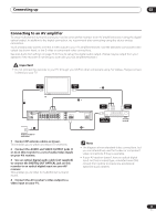
02 Connecting up Chapter 2 Connecting up Rear panel connections 1 2 3 4 56 7 INPUT 1/ IN AUTO START REC OUTPUT Y 1 1 PB DIGITAL CONTROL OUT AC IN OUT VHF/UHF R L AUDIO 3 VIDEO S-VIDEO R L AUDIO 2 VIDEO S-VIDEO PR COMPONENT VIDEO OUT OPTICAL IN 1 VHF/UHF IN/OUT Connect your TV antenna to the VHF/UHF IN jack. The signal is passed through to the VHF/UHF OUT jack for connection to your TV. 2 Audio/video inputs 1 and 3 Two sets of audio/video inputs (stereo analog audio; composite and S-video video) that you can use to connect to satellite receivers, TVs, VCR or other source component for recording. 3 Audio/video outputs 1 and 2 Two sets of audio/video outputs (stereo analog audio; composite and S-video video) that you can use to connect TVs or monitors. 4 COMPONENT VIDEO OUT A high-quality video output for connecting to a TV or monitor with a component video input. 5 DIGITAL OUT OPTICAL A digital audio output for connecting to an AV receiver, Dolby Digital/DTS decoder or other equipment with optical digital input. 6 CONTROL IN Use to control this recorder from the remote sensor of another Pioneer component with a CONTROL OUT terminal and bearing the Pioneer mark. Connect the CONTROL OUT of the other component to the CONTROL IN of this recorder using a mini-plug cord. 7 AC IN Connect to a power outlet using the supplied power cable after making all other connections. Front panel connections INPUT 2 S-VIDEO VIDEO DV IN/OUT VIDEO/R/RW On the left side of the front panel a flip-down cover hides a third audio/video input, consisting of an S-video and standard (composite) video jack, and stereo analog audio jacks. On the right side is the DV input/output i.LINK connector. This is for connection to a DV camcorder. 12 En
-
 1
1 -
2
-
3
-
4
-
5
-
6
-
 7
7 -
 8
8 -
 9
9 -
 10
10 -
 11
11 -
 12
12 -
 13
13 -
 14
14 -
 15
15 -
 16
16 -
 17
17 -
18
-
19
-
20
-
21
-
22
-
23
-
24
-
25
-
26
-
27
-
28
-
29
-
30
-
31
-
32
-
33
-
34
-
35
-
36
-
37
-
38
-
39
-
40
-
41
-
42
-
43
-
44
-
45
-
46
-
47
-
48
-
49
-
50
-
51
-
52
-
53
-
54
-
55
-
56
-
57
-
58
-
59
-
60
-
61
-
62
-
63
-
64
-
65
-
66
-
67
-
68
-
69
-
70
-
71
-
72
-
73
-
74
-
75
-
76
-
77
-
78
-
79
-
80
-
81
-
82
-
83
-
84
-
85
-
86
-
87
-
88
-
89
-
90
-
91
-
92
-
93
-
94
-
95
-
96
-
97
-
98
-
99
-
100
 |
 |
