Pioneer 504CMX Operating Instructions - Page 17
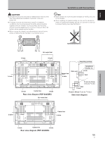
Rear view diagram PDP-504CMX, Side view diagram, Rear view diagram PDP-434CMX, CAUTION - pdp plasma
 |
UPC - 012562689784
View all Pioneer 504CMX manuals
Add to My Manuals
Save this manual to your list of manuals |
Page 17 highlights
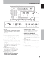
English Installation and Connections CAUTION ÷ Handles should not be removed or reattached by anyone other than the professional installation technician or service personnel. ÷ If handles must be removed due to specific installation conditions, the mounting screws should be stored carefully together with the handles. To ensure safety, the mounting screws should be tightened to a minimum torque of 2N·m (20 kgf·cm) when reattaching the handles. ÷ When moving the display, it should always be carried by two persons holding the rear handles in the manner shown. NO! ÷ Never attempt to move the plasma display by holding only one of the handles. ÷ When installing the plasma display, do not use the handles as means of hanging the display; also do not use them as devices to prevent tipping over (see illustration). Français Installation and Connections b hole b hole Air vents (fan) b hole a hole a hole b hole Center line b hole Rear view diagram (PDP-504CMX) Air vents (fan) Attaching surface Center line b hole Main unit Installation bracket, etc.. a hole Bolt 12 mm to 18 mm (1/2 in. to 11/16 in.) Bolt b hole 12 mm to 18 mm (1/2 in. to 11/16 in.) Side view diagram b hole a hole a hole Center line b hole b hole Center line b hole Rear view diagram (PDP-434CMX) 11 En
-
 1
1 -
2
-
3
-
4
-
5
-
6
-
7
-
8
-
9
-
10
-
11
-
 12
12 -
 13
13 -
 14
14 -
 15
15 -
 16
16 -
 17
17 -
 18
18 -
 19
19 -
 20
20 -
 21
21 -
 22
22 -
23
-
24
-
25
-
26
-
27
-
28
-
29
-
30
-
31
-
32
-
33
-
34
-
35
-
36
-
37
-
38
-
39
-
40
-
41
-
42
-
43
-
44
-
45
-
46
-
47
-
48
-
49
-
50
-
51
-
52
-
53
-
54
-
55
-
56
-
57
-
58
-
59
-
60
-
61
-
62
-
63
-
64
-
65
-
66
-
67
-
68
-
69
-
70
-
71
-
72
-
73
-
74
-
75
-
76
-
77
-
78
-
79
-
80
-
81
-
82
-
83
-
84
-
85
-
86
-
87
-
88
-
89
-
90
-
91
-
92
-
93
-
94
-
95
 |
 |
