Pioneer 607CMX Technical Manual - Page 167
COLOR MODE Setting
 |
UPC - 012562824413
View all Pioneer 607CMX manuals
Add to My Manuals
Save this manual to your list of manuals |
Page 167 highlights
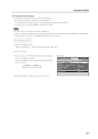
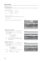
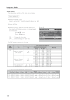
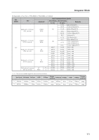
Integrator Mode 17) COLOR MODE Setting In addition to the normal operation mode (NORMAL), this display has a (STUDIO) mode for use in a TV studio. The adjustment values for 'PICTURE' and 'SCREEN' can be set independently. (Refer to section 5.4.4, "PICTURE, White Balance and SCREEN position Adjustment Values Memory Area Tables" (pg. 184).) Change the settings to meet the desired usage. Factory setting: NORMAL 1 Enter the integrator mode. (Refer to section 5.4.1, "About the Integrator Mode" (pg. 142).) 2 Select 'OPTION'. 3 Place the cursor on 'COLOR MODE' then press the [SET] button to change the setting. Each time the [SET] button is pressed, the setting changes as shown below. 3 NORMAL STUDIO 2 When the 'COLOR MODE' setting is changed, all input functions as well as the 'PICTURE' and 'SCREEN' adjustment values for the input signal are changed. Screen 3 I N T E G R ATO R INPUT1 PICTURE SCREEN SETUP OPTION F AN CONTROL : AUTO OSD F RO N T I N D I C ATO R : C O L O R MOD E : PRO USE FRC : ON NORMAL ON SET CHANGE MENU EXIT The 'COLOR MODE' setting is common for all inputs. 167
-
 1
1 -
2
-
3
-
4
-
5
-
6
-
7
-
8
-
9
-
10
-
11
-
12
-
13
-
14
-
15
-
16
-
17
-
18
-
19
-
20
-
21
-
22
-
23
-
24
-
25
-
26
-
27
-
28
-
29
-
30
-
31
-
32
-
33
-
34
-
35
-
36
-
37
-
38
-
39
-
40
-
41
-
42
-
43
-
44
-
45
-
46
-
47
-
48
-
49
-
50
-
51
-
52
-
53
-
54
-
55
-
56
-
57
-
58
-
59
-
60
-
61
-
62
-
63
-
64
-
65
-
66
-
67
-
68
-
69
-
70
-
71
-
72
-
73
-
74
-
75
-
76
-
77
-
78
-
79
-
80
-
81
-
82
-
83
-
84
-
85
-
86
-
87
-
88
-
89
-
90
-
91
-
92
-
93
-
94
-
95
-
96
-
97
-
98
-
99
-
100
-
101
-
102
-
103
-
104
-
105
-
106
-
107
-
108
-
109
-
110
-
111
-
112
-
113
-
114
-
115
-
116
-
117
-
118
-
119
-
120
-
121
-
122
-
123
-
124
-
125
-
126
-
127
-
128
-
129
-
130
-
131
-
132
-
133
-
134
-
135
-
136
-
137
-
138
-
139
-
140
-
141
-
142
-
143
-
144
-
145
-
146
-
147
-
148
-
149
-
150
-
151
-
152
-
153
-
154
-
155
-
156
-
157
-
158
-
159
-
160
-
161
-
 162
162 -
 163
163 -
 164
164 -
 165
165 -
 166
166 -
 167
167 -
 168
168 -
 169
169 -
 170
170 -
 171
171 -
 172
172 -
173
-
174
-
175
-
176
-
177
-
178
-
179
-
180
-
181
-
182
-
183
-
184
-
185
-
186
-
187
-
188
-
189
-
190
-
191
-
192
-
193
-
194
-
195
-
196
-
197
-
198
-
199
-
200
-
201
-
202
-
203
-
204
-
205
-
206
-
207
-
208
-
209
-
210
-
211
-
212
-
213
-
214
-
215
 |
 |