Pioneer 607CMX Technical Manual - Page 190
RS-232C Adjustment
 |
UPC - 012562824413
View all Pioneer 607CMX manuals
Add to My Manuals
Save this manual to your list of manuals |
Page 190 highlights
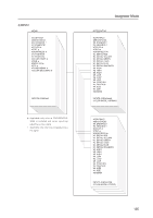
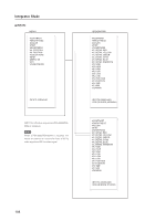
RS-232C Adjustment 5.5.2 Interface 1) Connector D-sub 9 pins (male/straight) 2) Pin layout Pin No. 1 2 3 4 5 Signal NC (not connected) TxD (Transmit Data) RxD (Receive Data) NC (not connected) GND Pin No. 6 7 8 9 Signal NC (not connected) NC (not connected) RTS (Request To Send) NC (not connected) 3) Baud Rate 9 600 bps (standard) (switch-able to 1 200, 2 400, 4 800, 19 200, 38 400 bps) 1 5 6 9 Note The baud rate of this display should be set to match the baud rate of the PC. Also, when the RS-232C cable is extended over a long distance, use a slower baud rate. 4) Data format Start bit: 1 bit Data bit: 8 bit Parity: no Stop bit: 1 bit 5) Connection Control PC (with D25 serial port ) Plasma Display Control PC (with D9 serial port) Plasma Display RXD 3 2 TXD 2 3 CTS 5 2 GND 7 2 TXD 3 RXD 8 RTS 5 GND RXD 2 2 TXD 3 3 CTS 8 2 GND 5 2 TXD 3 RXD 8 RTS 5 GND * D-sub 9-pin/D-sub 25-pin conversion tables are now available on the market. 6) Protocol From the PC to the display (1) Sending one command at a time: STX (02 hex) ID (2 Byte) COMMAND (3 Byte or 6 Byte) ETX (03 hex) Straight Cable (2) Sending numerical direct commands: STX (02 hex) ID (2 Byte) COMMAND (3 Byte) ARGUMENT (3 Byte) ETX (03 hex) ID, COMMAND, ARGUMENT are transmitted as ASCII characters. From the display to a PC (1) Echo back (Normal response) Command received and returned but the ID is not returned. STX (02 hex) COMMAND (3 Byte or 6 Byte) ETX (03 hex) Received command is a numerical direct effect command and numerical data is returned: STX (02 hex) COMMAND (3 Byte) ARGUMENT (3 Byte) ETX (03 hex) (2) Error (Abnormal response) Received command is a non-corresponding command, 'ERR' is returned: STX (02 hex) ERR (3 Byte) ETX (03 hex) Received command cannot be processed (when PON is received when the power is already ON, etc.), 'XXX' is returned: STX (02 hex) 190 XXX (3 Byte) ETX (03 hex)
-
 1
1 -
2
-
3
-
4
-
5
-
6
-
7
-
8
-
9
-
10
-
11
-
12
-
13
-
14
-
15
-
16
-
17
-
18
-
19
-
20
-
21
-
22
-
23
-
24
-
25
-
26
-
27
-
28
-
29
-
30
-
31
-
32
-
33
-
34
-
35
-
36
-
37
-
38
-
39
-
40
-
41
-
42
-
43
-
44
-
45
-
46
-
47
-
48
-
49
-
50
-
51
-
52
-
53
-
54
-
55
-
56
-
57
-
58
-
59
-
60
-
61
-
62
-
63
-
64
-
65
-
66
-
67
-
68
-
69
-
70
-
71
-
72
-
73
-
74
-
75
-
76
-
77
-
78
-
79
-
80
-
81
-
82
-
83
-
84
-
85
-
86
-
87
-
88
-
89
-
90
-
91
-
92
-
93
-
94
-
95
-
96
-
97
-
98
-
99
-
100
-
101
-
102
-
103
-
104
-
105
-
106
-
107
-
108
-
109
-
110
-
111
-
112
-
113
-
114
-
115
-
116
-
117
-
118
-
119
-
120
-
121
-
122
-
123
-
124
-
125
-
126
-
127
-
128
-
129
-
130
-
131
-
132
-
133
-
134
-
135
-
136
-
137
-
138
-
139
-
140
-
141
-
142
-
143
-
144
-
145
-
146
-
147
-
148
-
149
-
150
-
151
-
152
-
153
-
154
-
155
-
156
-
157
-
158
-
159
-
160
-
161
-
162
-
163
-
164
-
165
-
166
-
167
-
168
-
169
-
170
-
171
-
172
-
173
-
174
-
175
-
176
-
177
-
178
-
179
-
180
-
181
-
182
-
183
-
184
-
 185
185 -
 186
186 -
 187
187 -
 188
188 -
 189
189 -
 190
190 -
 191
191 -
 192
192 -
 193
193 -
 194
194 -
 195
195 -
196
-
197
-
198
-
199
-
200
-
201
-
202
-
203
-
204
-
205
-
206
-
207
-
208
-
209
-
210
-
211
-
212
-
213
-
214
-
215
 |
 |
