Pioneer DJM 3000 Owner's Manual - Page 8
Part Names And Functions - parts
 |
UPC - 012562585734
View all Pioneer DJM 3000 manuals
Add to My Manuals
Save this manual to your list of manuals |
Page 8 highlights
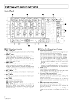
PART NAMES AND FUNCTIONS Control Panel ¥ ø π [ 1 7 7 7 7 8 98 98 98 9 @ ^ 0 0 0 0# 2 = -= -= -= - 3 $ ~ ~ ~ ~ 4 ! ! ! ! % 5 6 " & ] * ( _ +¡ ™ £ ' ¥ MIC (Microphone Controls) 1 MIC 1 input jack Use to connect a microphone with either XLR or PHONE type jack. 2 TREBLE control Adjusts high-range frequencies on microphone 1 and 2. Center click position is provided for flat response. Rotate the knob clockwise to augment treble response (to +12dB), and rotate counterclockwise to diminish treble response (to -12 dB). 3 BASS control Adjusts low-range frequencies on microphone 1 and 2. Center click position is provided for flat response. Rotate the knob clockwise to augment bass response (to +12dB), and rotate counterclockwise to diminish base response (to -12 dB). 4 MIC 1 LEVEL Controls sound volume on microphone 1 (attenuation: -∞ to 0 dB) 5 MIC 2 LEVEL Controls sound volume on microphone 2 (attenuation: -∞ to 0 dB) 6 MIC switch Use to select microphone input. OFF: Disables microphone 1 and 2 ON: Enables microphone 1 and 2 TALK OVER: Enables microphone 1 and 2 while attenuating other sound levels. The amount of attenuation can be controlled by setting the rear-panel TALK OVER LEVEL, within the range -4 dB to -20 dB. ) ¢ \ ø CH-1 to CH-4 (Channel Input Controls) 7 Input selector switches Use to select an input source from among the components connected to the various channels. CH-1: Switches between LINE 1 and PHONO 1/LINE 2 CH-2: Switches between LINE 3 and PHONO 2/LINE 4 CH-3: Switches between LINE 5 and PHONO 3/LINE 6 CH-4: Switches between LINE 7 and MIC 3/PHONO 4 ¶ On CH-1 to CH-3, the rear panel PHONO/LINE switches are used to switch between PHONO 1, 2, 3 and LINE 2, 4, and 6. ¶ On CH-4, switching between MIC 3 and PHONO 4 is based on the presence/absence of a plug in the MIC 3 connector (when a plug is inserted, MIC 3 is selected). 8 TRIM control Use to control the input signal level. Rotate clockwise to increase the level (to +9 dB); rotate counterclockwise to decrease the level (to -∞) 9 HI control (high-range equalizer) Use to adjust high-range frequency of input. When the dial is set to the center click setting, flat response is provided. Rotate clockwise to increase response (to +12 dB), and rotate counterclockwise to decrease response (to -26 dB). 0 MID control (mid-range equalizer) Use to adjust mid-range frequency of input. When the dial is set to the center click setting, flat response is provided. Rotate clockwise to increase response (to +12 dB), and rotate counterclockwise to decrease response (to -26 dB). 8
-
 1
1 -
2
-
 3
3 -
 4
4 -
 5
5 -
 6
6 -
 7
7 -
 8
8 -
 9
9 -
 10
10 -
 11
11 -
 12
12 -
 13
13 -
14
-
15
-
16
-
17
-
18
-
19
-
20
-
21
-
22
-
23
-
24
-
25
-
26
-
27
-
28
 |
 |
