Pioneer DJM-800 Owner's Manual - Page 10
Names And Functions Of Parts Operation Panel
 |
UPC - 012562796604
View all Pioneer DJM-800 manuals
Add to My Manuals
Save this manual to your list of manuals |
Page 10 highlights
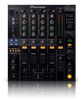
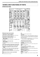
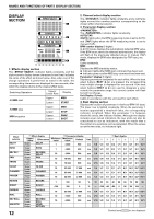
NAMES AND FUNCTIONS OF PARTS (OPERATION PANEL) 11. TRIM adjust dial Use to adjust the input level for each channel. (adjustable range: -∞ to +9 dB, mid-position is about 0 dB) 12. Channel equalizer high-range adjust dial (HI) Use to adjust the treble (high-range) frequency sound for each channel. (adjustable range: -26 dB to +6 dB) 13. Channel equalizer mid-range adjust dial (MID) Use to adjust the mid-range frequency sound for each channel. (adjustable range: -26 dB to +6 dB) 14. Channel equalizer low-range adjust dial (LOW) Use to adjust the bass (low-range) frequency sound for each channel. (adjustable range: -26 dB to +6 dB) 15. Channel level indicator Displays the current level for each channel, with two-second peak hold. 16. Headphone CUE buttons/indicators These buttons are used to select from channel 1 to 4, MASTER, or effector, to allow you to monitor the desired source through headphones. If multiple buttons are pressed simultaneously, the selected audio sources are mixed. Press the button once more to cancel the selected source. Unselected buttons glow darkly, while selected source buttons light brightly. Fader control section 17. Fader start button/indicator (FADER START 1 to 4) Enables the fader start/back cue function for the channel to which a DJ CD player is connected. The button lights when set to ON. When enabled, the operation differs depending on the setting of the CROSS FADER ASSIGN switch. ¶ When the CROSS FADER ASSIGN switch is set to the [A] or [B] position, fader start button operation is linked to the operation of the cross fader (and unlinked to channel fader). ¶ When the CROSS FADER ASSIGN switch is set to the [THRU] position, fader start button operation is linked to the operation of the channel fader (and unlinked to cross fader). 18. Channel fader lever Use to adjust sound volumes for each channel. (adjustable range: -∞ to 0 dB) Output is in accordance with the channel fader curve selected with the CH FADER curve switch. 19. CROSS FADER ASSIGN switch This switch assigns each channel's output to either right or left side of the cross fader (if multiple channels are assigned to the same side, the result will be the combined sum of the channels). A: The selected channel is assigned to the cross fader's A (left) side. THRU: The channel fader's output is sent as is to the master output, without being passed through the cross fader. B: The selected channel is assigned to the cross fader's B (right) side. 20. Channel fader curve switch (CH FADER) This switch allows the user to select from three types of channel fader curve response. This setting is applied equally to channels 1 to 4. ¶ At the left setting, the curve operates to produce a rapid rise as the channel fader approaches its distant position. ¶ At the right setting, the curve operates to produce an even, neutral rise throughout the channel fader's movement. ¶ At the middle setting, an intermediate curve is produced, midway between the two curves noted above. 10 21. Cross fader curve switch (CROSS FADER) This switch allows the user to select from three types of cross fader curve response. ¶ At the left setting, the curve produces a rapid signal rise. (As soon as the cross fader lever leaves the [A] side, the [B] channel sound is produced.) ¶ At the right setting, the curve operates to produce an even, neutral rise throughout the cross fader's movement. ¶ At the middle setting, an intermediate curve is produced, midway between the two curves noted above. 22. Cross fader lever Outputs sound assigned to [A] and [B] sides in accordance with setting of the CROSS FADER ASSIGN switch, and subject to the cross fader curve selected with the CROSS FADER curve switch. Master output control section 23. Master output level dial (MASTER LEVEL) Use to adjust the master output level. (adjustable range: -∞ to 0 dB) The master output is the sum combination of the sound from channels set to [THRU] with the CROSS FADER ASSIGN switch; the signal passed through the cross fader; and the signals from microphone 1 and microphone 2 (if the effect selector is set to [SND/RTN], the RETURN input is also added). 24. Master level indicator (MASTER L, R) These segment indicators display the output level from L and R channels. The indicators have a two-second peak hold. 25. Master balance dial (BALANCE) Use to adjust the L/R channel balance for master output, booth monitor output, recording output, and digital output. 26. Master output STEREO/MONO selector switch When set to [MONO], the master output becomes a monaural combination of L+R. Booth monitor control section 27. BOOTH MONITOR level control dial This dial is used to adjust the booth monitor output volume. The volume can be adjusted independently of the master output level. (adjustable range: -∞ to 0 dB) Headphones output section 28. Headphones output switch (MONO SPLIT/STEREO) MONO SPLIT: The audio source selected with the headphone CUE button is output to the L channel, and the master audio is output to the R channel (only when headphone CUE button is used to select [MASTER]). STEREO: The audio source selected with the headphone CUE button is output in stereo. 29. Headphones mixing dial (MIXING) When rotated clockwise (toward [MASTER]), the master output audio is produced at the headphones (only when [MASTER] has been selected with the headphones CUE button); when rotated counterclockwise (toward [CUE]), the headphones output becomes the mixture of the effect monitor and the channel selected with the headphone CUE button.
-
 1
1 -
2
-
3
-
4
-
 5
5 -
 6
6 -
 7
7 -
 8
8 -
 9
9 -
 10
10 -
 11
11 -
 12
12 -
 13
13 -
 14
14 -
 15
15 -
16
-
17
-
18
-
19
-
20
-
21
-
22
-
23
-
24
 |
 |