Pioneer DJM-800 Owner's Manual - Page 6
Connecting Inputs - player
 |
UPC - 012562796604
View all Pioneer DJM-800 manuals
Add to My Manuals
Save this manual to your list of manuals |
Page 6 highlights
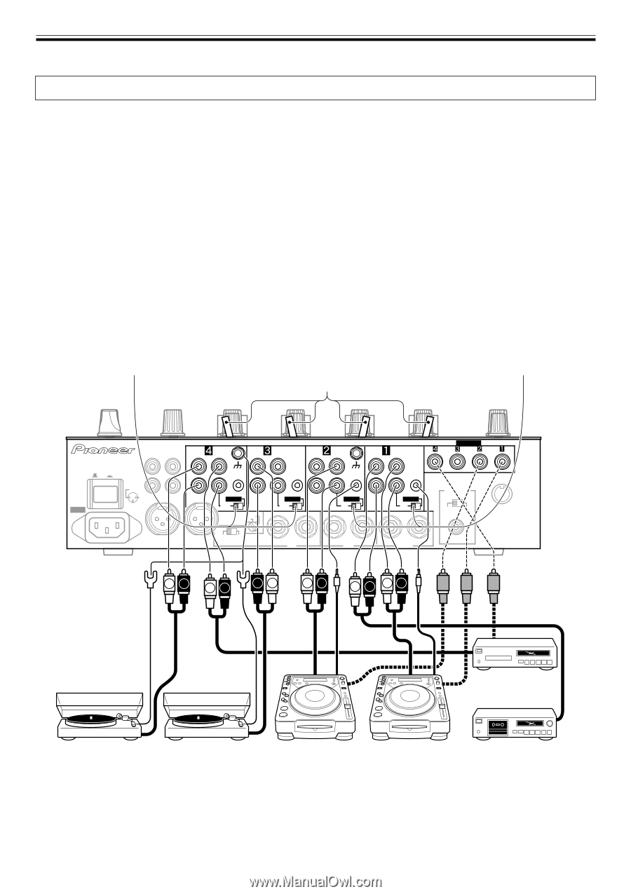
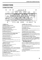
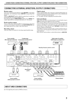
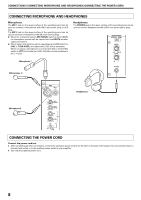
CONNECTIONS (CONNECTING INPUTS) Always turn off the power switch and disconnect the power plug from its outlet when making or changing connections. CONNECTING INPUTS Pioneer DJ CD players Connect a DJ CD player's audio output connectors to one of the channel 1 to 2 CD input connectors or the channel 3 to 4 LINE input connectors, and connect the player's control cable to the corresponding channel's CONTROL connector. Set the connected channel's DIGITAL/CD switch or DIGITAL/LINE switch to either [CD] or [LINE], and set the input selector switch to [CD/DIGITAL] or [LINE/DIGITAL]. When making digital connections, connect the digital coaxial output terminal of the DJ CD player to one of the channel 1 to 4 DIGITAL IN connectors of the DJM-800; then set the corresponding channel's DIGITAL/CD switch or DIGITAL/LINE switch to [DIGITAL], and the input selector switch to [CD/DIGITAL] or [LINE/DIGITAL]. Analog turntable To connect an analog turntable, connect the turntable's audio output cable to one of the channel 2 to 4 PHONO input connectors. Set the corresponding channel's input selector switch to [PHONO]. The DJM-800's PHONO inputs support MM cartridges. Connect the turntable's ground wire to one of the DJM-800's SIGNAL GND terminals. ÷ Note that no PHONO input connector is provided for channel 1. Connecting other line level output devices To use a cassette deck or other CD player, connect the component's audio output connectors to one of the channel 3 to 4 LINE input connectors. Then set the corresponding channel's DIGITAL/LINE switch to [LINE], and the input selector switch to [LINE/DIGITAL]. Alternately, connect the component to the channel 1 LINE input connector, then set the channel 1 input selector switch to [LINE]. Connecting other digital output devices To use a CD player or other component with digital connections, connect the component's digital coaxial output connectors to one of the channel 1 to 4 DIGITAL IN connectors; then set the corresponding channel's DIGITAL/CD switch or DIGITAL/LINE switch to [DIGITAL], and the input selector switch to [CD/DIGITAL] or [LINE/DIGITAL]. ÷ The sound may be temporarily interrupted when the output signal's sampling frequency is changed. DIGITAL/LINE switch Input selector switch DIGITAL/CD switch AC IN POWER OFF ON MASTER 2 REC L 1GND R 2HOT 3COLD SIGNAL GND PHONO LINE L PHONO LINE L SIGNAL GND PHONO CD L LINE CD L CONTROL CONTROL CONTROL CONTROL R R DIGITAL LINE MASTER ATT -3dB0dB -6dB -12dB DIGITAL LINE R DIGITAL CD R DIGITAL CD DIGITAL IN DIGITAL OUT fs (Hz) 48 k 96 k MIDI OUT R MASTER 1 L ADD CUT MIC SIGNAL R BOOTH (TRS) L R SEND L(MONO) R RETURN L(MONO) LR LR RL LR LR LR CD player, etc. Analog turntable Analog turntable DJ CD player DJ CD player Cassette deck, etc. 6
-
 1
1 -
 2
2 -
 3
3 -
 4
4 -
 5
5 -
 6
6 -
 7
7 -
 8
8 -
 9
9 -
 10
10 -
 11
11 -
 12
12 -
13
-
14
-
15
-
16
-
17
-
18
-
19
-
20
-
21
-
22
-
23
-
24
 |
 |