Pioneer DJM-800 Owner's Manual - Page 12
Display, - parts
 |
UPC - 012562796604
View all Pioneer DJM-800 manuals
Add to My Manuals
Save this manual to your list of manuals |
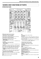
Page 12 highlights
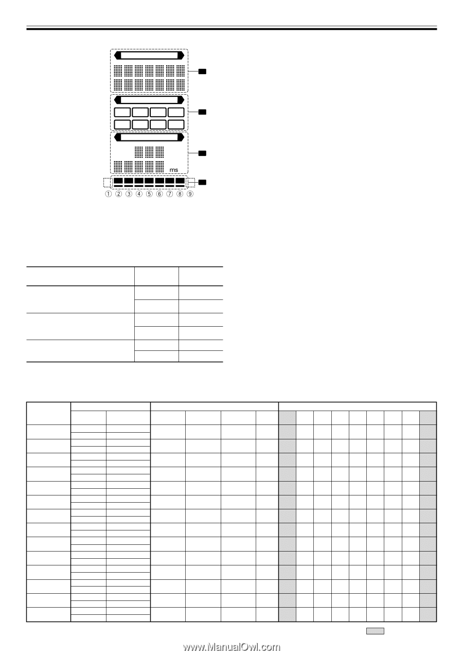
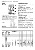
NAMES AND FUNCTIONS OF PARTS (DISPLAY SECTION) DISPLAY SECTION EFFECT SELECT 1 CH SELECT 1234 2 MIC A B MST PARAMETER AUTO TAP MIDI BPM 3 % 4 1. Effects display section The indicator lights constantly, and the alpha-numeric display (seven characters in two lines) indicates the name of the effect as shown below. Also, when one of the change operations is performed as noted in the table, the corresponding characters are displayed for two seconds, after which the display returns to the original effect name. Switching Operation Upper/ Lower Row Display At MIDI start Upper Lower MIDI START At MIDI stop MIDI snapshot Upper Lower Upper Lower MIDI STOP SNAP SHOT 2. Channel select display section The indicator lights constantly, and a red frame lights around the number position corresponding to the chosen effect channel selector. 3. Parameter display section : The indicator lights constantly. AUTO/TAP: [AUTO] lights when the BPM measuring mode is set to AUTO, and [TAP] lights when the BPM measuring mode is set to manual (TAP). BPM counter display (3 digits): In AUTO mode, displays the automatically detected BPM value. If the BPM count cannot be detected automatically, the display will flash at the previously detected value. In manual (TAP) mode, displays the BPM value designated by TAP input, etc. BPM: Lights constantly. MIDI: Displays the MIDI start/stop status. ¶ Indicator lights after MIDI start command has been sent. ¶ Indicator goes out after MIDI stop command has been sent. Parameter 1 display (5 digits): Displays parameters designated for each effect. When the beat select buttons (BEAT 2, 3) are pressed, the corresponding beat multiple change is displayed for one second. If the beat select buttons (BEAT 2, 3) are used to designate a value outside the parameter range, the current number will flash but will not change. Unit Display (%/ms): Lights in accordance with the unit used for each effect. 4. Beat display section Displays the location of parameter 1 relative to BPM (1/1 beat). The lower row is lighted constantly. When the parameter 1 location approaches a threshold value, the corresponding indicator is lighted. When the parameter 1 is between threshold values, the indicator flashes. Although the display includes seven actual indicators, the two ends can also be considered to act as indicators, with the result that a theoretical nine positions can be postulated. When the values are at the two ends, no indicators light. Effect selector DELAY ECHO REV DLY PAN TRANS FILTER FLANGER PHASER REVERB ROBOT CHORUS ROLL REV ROLL SND/RTN 12 1 Effect display Upper/ Lower Effect name Upper DELAY Lower Upper ECHO Lower Upper REVERSE Lower DELAY Upper PAN Lower Upper TRANS Lower Upper FILTER Lower Upper FLANGER Lower Upper PHASER Lower Upper REVERB Lower Upper ROBOT Lower Upper CHORUS Lower Upper ROLL Lower Upper REVERSE Lower ROLL Upper SEND/ Lower RETURN Minimum value 1 1 10 10 10 10 10 10 1 -100 10 10 10 3 Parameter display Maximum value Default 4 000 500 4 000 500 4 000 500 16 000 500 16 000 500 32 000 2 000 32 000 2 000 32 000 2 000 100 50 100 0 32 000 2 000 4 000 500 4 000 500 4 Beat display Unit 1 2 3 4 5 6 7 8 9 ms 1/8 1/4 1/2 3/4 1/1 2/1 4/1 8/1 16/1 ms 1/8 1/4 1/2 3/4 1/1 2/1 4/1 8/1 16/1 ms 1/8 1/4 1/2 3/4 1/1 2/1 4/1 8/1 16/1 ms 1/16 1/8 1/4 1/2 1/1 2/1 4/1 8/1 16/1 ms 1/16 1/8 1/4 1/2 1/1 2/1 4/1 8/1 16/1 ms 1/4 1/2 1/1 2/1 4/1 8/1 16/1 32/1 64/1 ms 1/4 1/2 1/1 2/1 4/1 8/1 16/1 32/1 64/1 ms 1/4 1/2 1/1 2/1 4/1 8/1 16/1 32/1 64/1 % 10 20 30 40 50 60 70 80 90 % - -100 -66 -50 0 26 50 100 - ms 1/4 1/2 1/1 2/1 4/1 8/1 16/1 32/1 64/1 ms 1/16 1/8 1/4 1/2 1/1 2/1 4/1 8/1 16/1 ms 1/16 1/8 1/4 1/2 1/1 2/1 4/1 8/1 16/1 Shaded items are not displayed.
-
 1
1 -
2
-
3
-
4
-
5
-
6
-
 7
7 -
 8
8 -
 9
9 -
 10
10 -
 11
11 -
 12
12 -
 13
13 -
 14
14 -
 15
15 -
 16
16 -
 17
17 -
18
-
19
-
20
-
21
-
22
-
23
-
24
 |
 |