Pioneer PRS-D800 Owner's Manual - Page 7
Connection diagram, Before connecting the, amplifier, Connecting the units
 |
View all Pioneer PRS-D800 manuals
Add to My Manuals
Save this manual to your list of manuals |
Page 7 highlights
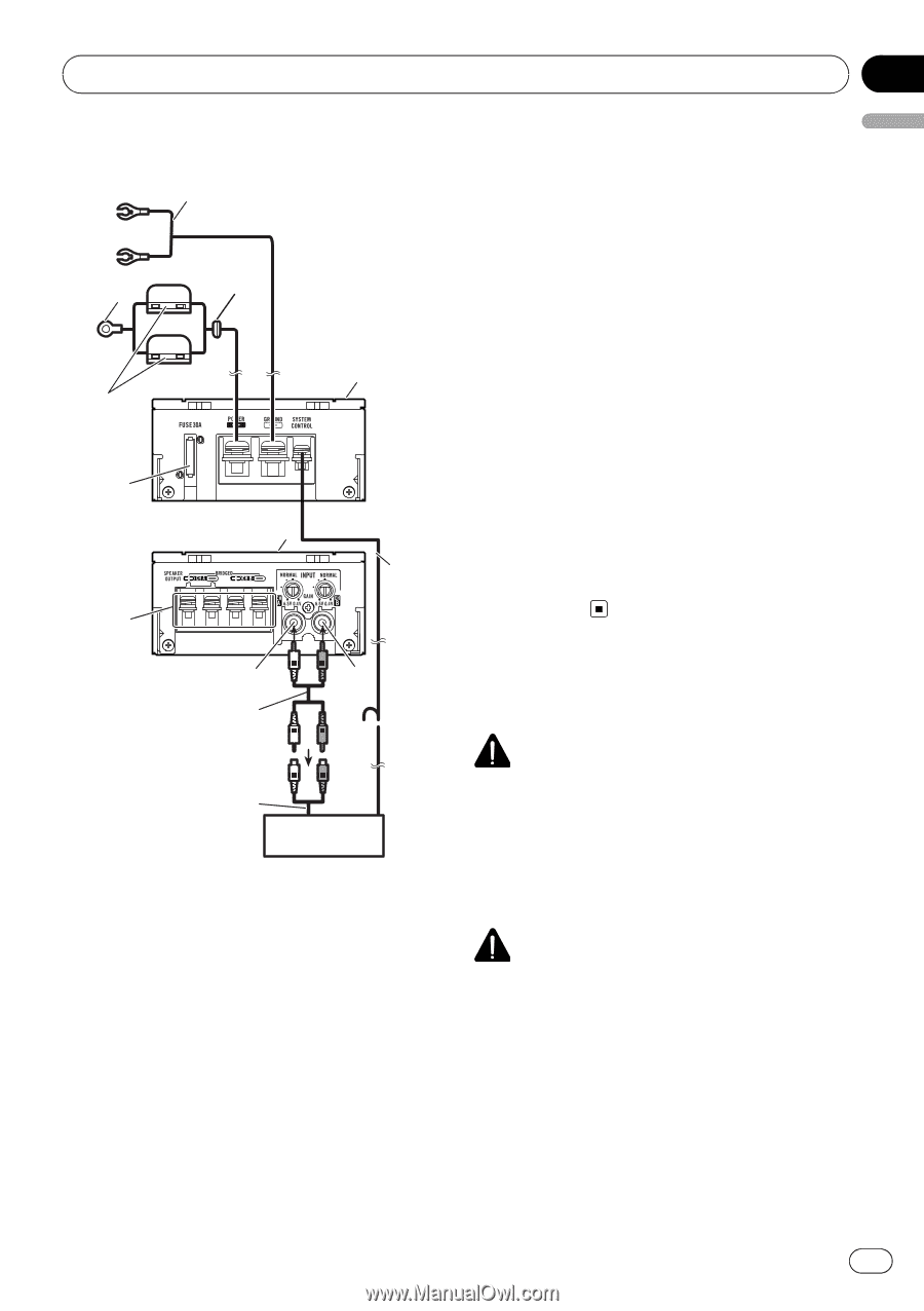
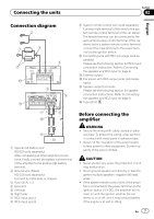
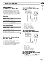
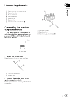
Connecting the units Section 02 English Connection diagram 2 1 4 5 3 e 6 9 d 7L a R8 b c 1 Special red battery wire RD-223 (sold separately) After completing all other amplifier connections, finally connect the battery wire terminal of the amplifier to the positive (+) battery terminal. 2 Ground wire (Black) RD-223 (sold separately) Connect to metal body or chassis. 3 Fuse (30 A) × 2 4 Grommet 5 Left side 6 Right side 7 RCA input jack A 8 RCA input jack B 9 System remote control wire (sold separately) Connect male terminal of this wire to the system remote control terminal of the car stereo. The female terminal can be connected to the auto-antenna relay control terminal. If the car stereo lacks a system remote control terminal, connect the male terminal to the power terminal via the ignition switch. a Connecting wire with RCA pin plugs (sold separately) Please see the following section for RCA input connection instruction. Refer to Connecting the speakers and RCA input on page 9. b External output c Car stereo with RCA output jacks (sold sepa- rately) d Speaker output terminals Please see the following section for speaker connection instructions. Refer to Connecting the speakers and RCA input on page 9. e Fuse (30 A) Before connecting the amplifier WARNING ! Secure the wiring with cable clamps or adhe- sive tape. To protect the wiring, wrap sections in contact with metal parts in adhesive tape. ! Never cut the insulation of the power supply to feed power to other equipment. Current capacity of the wire is limited. CAUTION ! Never shorten any wires, the protection circuit may malfunction. ! Never ground speaker wire directly or band to- gether multiple speakers' negative (*) lead wires. ! If the system remote control wire of the amplifier is connected to the power terminal via the ignition switch (12 V DC), the amplifier will remain on with the ignition whether the car stereo is on or off, which may exhaust battery if the engine is at rest or idling. En 7
-
 1
1 -
 2
2 -
 3
3 -
 4
4 -
 5
5 -
 6
6 -
 7
7 -
 8
8 -
 9
9 -
 10
10 -
 11
11 -
 12
12 -
13
-
14
-
15
-
16
-
17
-
18
-
19
-
20
-
21
-
22
-
23
-
24
-
25
-
26
-
27
-
28
-
29
-
30
-
31
-
32
-
33
-
34
-
35
-
36
-
37
-
38
-
39
-
40
 |
 |