Pioneer PRS-D800 Owner's Manual - Page 8
About bridged mode, Connecting the units
 |
View all Pioneer PRS-D800 manuals
Add to My Manuals
Save this manual to your list of manuals |
Page 8 highlights
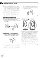
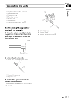
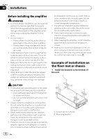
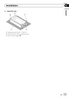
Section 02 Connecting the units ! Install and route the separately sold battery wire as far as possible from the speaker wires. Install and route the separately sold battery wire, ground wire, speaker wires and the amplifier as far away as possible from the antenna, antenna cable and tuner. ! Avoid routing wires through hot areas, such as near the heater outlet. Heat may damage the insulation, resulting in a short-circuit through the vehicle body. Removal of the terminal cover Before connecting and installing the amplifier, you need to remove the terminal cover. 1 Slide the terminal cover outward (M) and pull it toward (N) you. Make sure that the hook on the terminal cover has been inserted firmly into this unit. Refer to the illustration for details. About bridged mode Reattachment of the terminal cover 1 With the terminal cover slid open, attach the cover as shown in the illustration below. 2 Press on the upper sides of the terminal cover to make sure that the cover is firmly attached to this unit. 3 Press on the lower sides of the terminal cover. The maximum speaker impedance is 4 W. Please carefully check. Improper connection to the amplifier may result in malfunction or personal injury due to burns from overheating. For bridged mode for a two-channel amplifier, with a 4 W load, either wire two 8 W speakers in parallel, Left + and Right * (Diagram A) or use a single 4 W speaker. For other amplifiers, please follow the speaker output connection diagram for bridging shown on rear: two 8 W speakers in parallel for a 4 W load or a single 4 W speaker per channel. For any further enquiries, contact your local authorized Pioneer dealer or customer service. 8 En
-
 1
1 -
2
-
 3
3 -
 4
4 -
 5
5 -
 6
6 -
 7
7 -
 8
8 -
 9
9 -
 10
10 -
 11
11 -
 12
12 -
 13
13 -
14
-
15
-
16
-
17
-
18
-
19
-
20
-
21
-
22
-
23
-
24
-
25
-
26
-
27
-
28
-
29
-
30
-
31
-
32
-
33
-
34
-
35
-
36
-
37
-
38
-
39
-
40
 |
 |