Pioneer PRS-X340 Owners Manual - Page 6
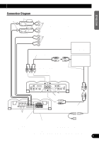
Connecting the Unit - manual
 |
View all Pioneer PRS-X340 manuals
Add to My Manuals
Save this manual to your list of manuals |
Page 6 highlights
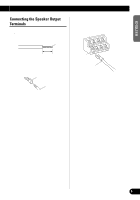
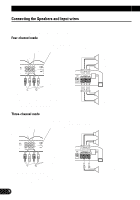
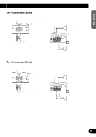
Connecting the Unit CAUTION • Disconnect the negative (-) terminal of the battery to avoid the risk of short-circuit and damage to the unit. • Secure the wiring with cable clamps or adhesive tape. To protect the wiring, wrap adhesive tape around it where they lie against metal parts. • Do not route wires where they will get hot, for example where the heater will blow over them. If the insulation heats up, it may become damaged, resulting in a short-circuit through the vehicle body. • Make sure that wires will not interfere with moving parts of the vehicle, such as the gearshift, handbrake or seat sliding mechanism. • Do not shorten any wires. Otherwise the protection circuit may fail to work when it should. • Never feed power to other equipment by cutting the insulation of the power supply wire to tap from the wire. The current capacity of the wire will be exceeded, causing overheating. To prevent damage • Do not ground the speaker wire directly or connect a negative (-) lead wire for several speakers. • This unit is for vehicles with a 12-volt battery and negative grounding. Before installing it in a recreational vehicle, truck or bus, check the battery voltage. • If the car stereo is kept on for a long time while the engine is at rest or idling, the battery may go dead. Turn the car stereo off when the engine is at rest or idling. • If the system remote control wire of the amplifier is connected to the power terminal through the ignition switch (12 V DC), the amplifier will always be on when the ignition is on- regardless of whether the car stereo is on or off. Because of this, the battery could go dead if the engine is at rest or idle. • Speakers to be connected to the amplifier should conform with the standards listed below. If they do not conform, they may catch fire, emit smoke or become damaged. The speaker impedance must be 1 to 8 ohms. But in case of two-channel and other bridge connections, the speaker impedance must be 2 to 8 ohms. • Install and route the separately sold battery wire as far away as possible from the speaker wires. Install and route the separately sold battery wire, ground wire, speaker wires and the amplifier as far away as possible from the antenna, antenna cable and tuner. • Cords for this product and those for other products may be different colors even if they have the same function. When connecting this product to another product, refer to the supplied Installation manuals of both products and connect cords that have the same function. Speaker Channel Four-channel Two-channel Three-channel Speaker output A Three-channel Speaker output B Speaker Type Subwoofer Other than subwoofer Subwoofer Other than subwoofer Subwoofer Other than subwoofer Subwoofer Other than subwoofer Power Nominal input: Min. 95 W Max. input: Min. 95 W Nominal input: Min. 330 W Max. input: Min. 330 W Nominal input: Min. 95 W Max. input: Min. 95 W Nominal input: Min. 330 W Max. input: Min. 330 W 5
-
 1
1 -
 2
2 -
 3
3 -
 4
4 -
 5
5 -
 6
6 -
 7
7 -
 8
8 -
 9
9 -
 10
10 -
 11
11 -
 12
12 -
13
-
14
-
15
-
16
-
17
-
18
-
19
-
20
-
21
-
22
-
23
-
24
-
25
-
26
-
27
-
28
-
29
-
30
-
31
-
32
-
33
-
34
-
35
-
36
-
37
-
38
-
39
-
40
-
41
-
42
-
43
-
44
-
45
-
46
-
47
-
48
-
49
-
50
-
51
-
52
-
53
-
54
-
55
-
56
-
57
-
58
-
59
-
60
-
61
-
62
-
63
-
64
-
65
-
66
-
67
-
68
-
69
-
70
-
71
-
72
-
73
-
74
-
75
-
76
-
77
-
78
-
79
-
80
-
81
-
82
-
83
-
84
-
85
-
86
-
87
-
88
 |
 |
