Pioneer SC-37 Owner's Manual - Page 14
RF adapter, Area indicating the remote control's status
 |
UPC - 884938108768
View all Pioneer SC-37 manuals
Add to My Manuals
Save this manual to your list of manuals |
Page 14 highlights
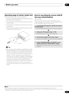
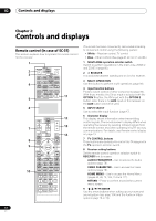
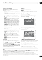
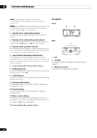
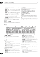
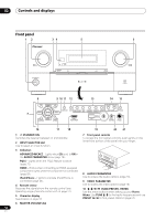
02 Controls and displays MAIN (Gray box with black letters): Two-way communications are established and the receiver's power is off. MAIN (White letters only): Two-way communications are not working well. In this case, the area indicating the receiver's status (12) is not displayed. 2 Remote control code sending indicator This appears when signals are sent from the remote control. 3 Remote control code sending mode indicator This indicates whether remote control codes are being sent by infrared (IR) signal or RF communications. 4 Remote control operation indicator This indicates which operation mode the remote control is currently set to. The display indicates the setting of the remote control operation selector switch. 5 Input function and sending code indicator This indicates what input function can currently be operated with the remote control. Also, when a button is pressed and its operation code is sent, the name of that code is displayed. 6 Area indicating the remote control's status 7 Nothing displayed Nothing is displayed here when the remote control code sending mode is set to IR. 8 Scroll indicators Light when there are more selectable items when making the various settings. 9 Receiver input indicator This indicates the input function currently selected for the receiver's zone. 10 Receiver display The same information as on the receiver's display is displayed here. 11 Master volume display This indicates the volume of the receiver's main zone using, as an icon and in decibels (dB). When the sound is muted, the icon is displayed. 12 Area indicating the receiver's status RF adapter Front 1 2 Rear 3 1 LED 2 SETTING Use to pairing the RF adapter and remote control (page 91). 3 IR blaster terminals Connect the IR blaster cable (page 92). 14 En
-
 1
1 -
2
-
3
-
4
-
5
-
6
-
7
-
8
-
 9
9 -
 10
10 -
 11
11 -
 12
12 -
 13
13 -
 14
14 -
 15
15 -
 16
16 -
 17
17 -
 18
18 -
 19
19 -
20
-
21
-
22
-
23
-
24
-
25
-
26
-
27
-
28
-
29
-
30
-
31
-
32
-
33
-
34
-
35
-
36
-
37
-
38
-
39
-
40
-
41
-
42
-
43
-
44
-
45
-
46
-
47
-
48
-
49
-
50
-
51
-
52
-
53
-
54
-
55
-
56
-
57
-
58
-
59
-
60
-
61
-
62
-
63
-
64
-
65
-
66
-
67
-
68
-
69
-
70
-
71
-
72
-
73
-
74
-
75
-
76
-
77
-
78
-
79
-
80
-
81
-
82
-
83
-
84
-
85
-
86
-
87
-
88
-
89
-
90
-
91
-
92
-
93
-
94
-
95
-
96
-
97
-
98
-
99
-
100
-
101
-
102
-
103
-
104
-
105
-
106
-
107
-
108
-
109
-
110
-
111
-
112
-
113
-
114
-
115
-
116
-
117
-
118
-
119
-
120
-
121
-
122
-
123
-
124
-
125
-
126
-
127
-
128
-
129
-
130
-
131
-
132
-
133
-
134
-
135
-
136
-
137
-
138
-
139
-
140
-
141
-
142
-
143
-
144
-
145
-
146
-
147
-
148
 |
 |
