Pioneer SC-37 Owner's Manual - Page 36
Connecting additional amplifiers, Connecting AM/FM antennas, antenna wires.
 |
UPC - 884938108768
View all Pioneer SC-37 manuals
Add to My Manuals
Save this manual to your list of manuals |
Page 36 highlights
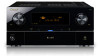
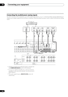
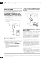
03 Connecting your equipment Connecting additional amplifiers This receiver has more than enough power for any home use, but it's possible to add additional amplifiers to every channel of your system using the pre-outs. Make the connections shown below to add amplifiers to power your speakers. Connecting AM/FM antennas Connect the AM loop antenna and the FM wire antenna as shown below. To improve reception and sound quality, connect external antennas (see Connecting external antennas on page 37). ANALOG INPUT L R Front channel amplifier 1 2 /100) XM ADAPTER PORT IN (OUTPUT 5 V 100 mA MAX) AL ASSIGNABLE OPTICAL ASSIGNABLE IN 2 IN 3 IN 1 IN 2 IN 3 (CD) (CD-R) (TV/SAT) (DVR/BDR) (VIDEO) OUT FRONT CENTER SURROUND SURR BACK FH/FW (Single) FRONT CENT SUBWOOFER PRE OUT SUBWO SURROUND BACK SURROUND L (Single) R L ANALOG INPUT ANALOG INPUT L R Center channel amplifier (mono) Surround channel amplifier ANALOG INPUT L R ANALOG INPUT L Front height or Front wide channel amplifier R ANALOG INPUT Surround back channel amplifier TION: R IMPEDANCE 6 Ω - 16 Ω . NTION: E D'IMPEDANCE DE 6 Ω - 16 Ω . Powered subwoofer • You can use the additional amplifier on the surround back channel pre-outs for a single speaker as well. In this case plug the amplifier into the left (L (Single)) terminal only. • The sound from the surround back terminals will depend on how you have configured the Speaker system setting on page 115. • To hear sound only from the pre-outs, switch the speaker system to OFF, or simply disconnect any speakers that are connected directly to the receiver. If you're not using a subwoofer, change the front speaker setting (see Speaker Setting on page 115) to LARGE. 3 ANTENNA 5 4 AM LOOP FM UNBAL 75 fig. a fig. b fig. c 1 Pull off the protective shields of both AM antenna wires. 2 Push open the tabs, then insert one wire fully into each terminal, then release the tabs to secure the AM antenna wires. 3 Fix the AM loop antenna to the attached stand. To fix the stand to the antenna, bend in the direction indicated by the arrow (fig. a) then clip the loop onto the stand (fig. b). • If you plan to mount the AM antenna to a wall or other surface, secure the stand with screws (fig. c) before clipping the loop to the stand. Make sure the reception is clear. 4 Place the AM antenna on a flat surface and in a direction giving the best reception. 5 Connect the FM wire antenna into the FM antenna socket. For best results, extend the FM antenna fully and fix to a wall or door frame. Don't drape loosely or leave coiled up. 36 En
-
 1
1 -
2
-
3
-
4
-
5
-
6
-
7
-
8
-
9
-
10
-
11
-
12
-
13
-
14
-
15
-
16
-
17
-
18
-
19
-
20
-
21
-
22
-
23
-
24
-
25
-
26
-
27
-
28
-
29
-
30
-
 31
31 -
 32
32 -
 33
33 -
 34
34 -
 35
35 -
 36
36 -
 37
37 -
 38
38 -
 39
39 -
 40
40 -
 41
41 -
42
-
43
-
44
-
45
-
46
-
47
-
48
-
49
-
50
-
51
-
52
-
53
-
54
-
55
-
56
-
57
-
58
-
59
-
60
-
61
-
62
-
63
-
64
-
65
-
66
-
67
-
68
-
69
-
70
-
71
-
72
-
73
-
74
-
75
-
76
-
77
-
78
-
79
-
80
-
81
-
82
-
83
-
84
-
85
-
86
-
87
-
88
-
89
-
90
-
91
-
92
-
93
-
94
-
95
-
96
-
97
-
98
-
99
-
100
-
101
-
102
-
103
-
104
-
105
-
106
-
107
-
108
-
109
-
110
-
111
-
112
-
113
-
114
-
115
-
116
-
117
-
118
-
119
-
120
-
121
-
122
-
123
-
124
-
125
-
126
-
127
-
128
-
129
-
130
-
131
-
132
-
133
-
134
-
135
-
136
-
137
-
138
-
139
-
140
-
141
-
142
-
143
-
144
-
145
-
146
-
147
-
148
 |
 |
