Pioneer VSX-D498 Owner's Manual - Page 9
Audio Components Connections - receiver manual
 |
View all Pioneer VSX-D498 manuals
Add to My Manuals
Save this manual to your list of manuals |
Page 9 highlights
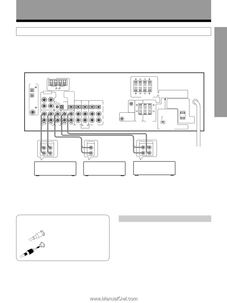
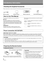
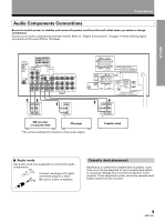
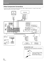
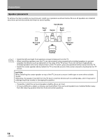
SET UP Connections Audio Components Connections Be sure to switch power to standby and remove the power cord from the wall outlet when you make or change connections. Connect your audio components as shown below. Refer to "Digital Connections" on page 11 when making digital connections from your DVD or LD player. ANTENNA DIGITAL IN PCM/ OPT 1 OPT 2 FM UNBAL 75Ω DVD 5.1 CH INPUT SURROUND L SUBWOOFER AM LOOP ANTENNA TO MONITOR TV CONTROL OUT IN VIDEO OUT IN IN PCM/ COAX R CENTER IN OUT IN IN OUT IN IN L IN OUT VIDEO IN OUT L R R PLAY REC MD/TAPE 1 PLAY REC CD TAPE 2 MONITOR TV/ DVD/ SAT LD DVD 5.1 CH FRONT VCR »« PLAY REC L L R R » OUTPUT L R R A L A B R B L FRONT SPEAKERS RL CAUTION: SPEAKER IMPEDANCE 6Ω OR 8Ω ~ 16Ω / SPEAKER ATTENTION: IMPEDANCE DE HAUT-PARLEURS 6Ω OU 8Ω ~ 16Ω / HAUT-PARLEUR CENTER PREOUT SUB WOOFER PREOUT CENTER SPEAKER RL SURROUND SPEAKERS CAUTION: ATTENTION: SEE INSTRUCTION SE REPOTER AU MANUAL MODE D'EMPLON 8~16Ω / SPEAKER 8~16Ω / HAUT- PARLEUR 6 ~ LESS THAN 8Ω /SPEAKER 6 ~ MOINS DE 8Ω /HAUT-PARLEUR IMPEDANCE SELECTOR » « PLAY REC L L R R MD recorder or Cassette deck CD player *The arrows indicate the direction of the audio signal. Cassette deck 7 Audio cords Use audio cords (not supplied) to connect the audio components. L Connect red plugs to R (right) and white plugs to L (left). R Be sure to insert completely. Cassette deck placement Depending on where the cassette deck is placed, noise may occur during playback of your cassette deck which is caused by leakage flux from the transformer in the receiver. If you experience noise, move the cassette deck farther away from the receiver. OPERA TION 9
-
 1
1 -
2
-
3
-
 4
4 -
 5
5 -
 6
6 -
 7
7 -
 8
8 -
 9
9 -
 10
10 -
 11
11 -
 12
12 -
 13
13 -
 14
14 -
15
-
16
-
17
-
18
-
19
-
20
-
21
-
22
-
23
-
24
-
25
-
26
-
27
-
28
-
29
-
30
-
31
-
32
-
33
-
34
-
35
-
36
-
37
-
38
-
39
-
40
-
41
-
42
-
43
-
44
-
45
-
46
-
47
-
48
 |
 |