ProForm 105 Cse Instruction Manual - Page 5
Part Identification Chart
 |
View all ProForm 105 Cse manuals
Add to My Manuals
Save this manual to your list of manuals |
Page 5 highlights
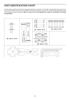
PART IDENTIFICATION CHART Use the drawings below to identify the small parts needed for assembly. The number in parentheses below each drawing is the key number of the part, from the PART LIST near the end of this manual. The number following the key number is the quantity needed for assembly. Note: If a part is not in the hardware kit, check to see whether it has been preassembled. 55 M8x15 2PCS 15 14 10 13 17 S19 S17 S17 34 M8x55 2PCS 37 M6x35 6PCS 29 M8x45 4PCS 14 13 5
-
 1
1 -
 2
2 -
 3
3 -
 4
4 -
 5
5 -
 6
6 -
 7
7 -
 8
8 -
 9
9 -
 10
10 -
 11
11 -
12
-
13
-
14
-
15
-
16
-
17
-
18
-
19
-
20
 |
 |

5
PART IDENTIFICATION CHART
Use the drawings below to identify the small parts needed for assembly. The number in parentheses below each draw-
ing is the key number of the part, from the PART LIST near the end of this manual. The number following the key number
is the quantity needed for assembly.
Note: If a part is not in the hardware kit, check to see whether it has been
preassembled.
34
M8x55
2PCS
37
M6x35
6PCS
29
M8x45
4PCS
S17
S17
S19
14
13
13
14
15
17
10
55
M8x15
2PCS