ProForm 920ci English Manual - Page 5
ProForm 920ci Manual
 |
View all ProForm 920ci manuals
Add to My Manuals
Save this manual to your list of manuals |
Page 5 highlights
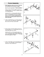
Frame Assembly 1. Before beginning, make sure that you have read and understood the information on page 4. Open the parts bag labeled "FRAME ASSEMBLY." Press a 2" Square Inner Cap (28) into each end of the Butterfly Base (4) and into the indicated locations on the Weight Base (5). 1 28 28 4 85 92 92 5 28 28 Insert four 5/16" x 2 1/2" Carriage Bolts (92) and a 3/8" x 3 3/4" Carriage Bolt (85) into the indicated holes in the Butterfly Base (4). Place the Butterfly Base flat on the floor. Note: If the Bolts fall out, secure them by putting a piece of tape over the head of each Bolt. 2. Attach the Weight Base (5) to the Butterfly Base (4) with two 5/16" x 2 3/4" Bolts (89), a Support Plate (94), and two 5/16" Nylon Locknuts (64). 2 89 94 64 4 64 5 3. Press a 2" Square Inner Cap (28) into each end of the Press Base (6). Turn the Press Base so the indicated welded tube is near the top. Insert four 5/16" x 2 1/2" Carriage Bolts (92) and a 3/8" x 4" Carriage Bolt (104) into the indicated holes in the Press Base (6). Note: The 3/8" x 4" Carriage Bolt will be tipped at an angle. 3 28 6 Welded Tube 28 92 92 104 4. Attach the Press Base (6) to the Weight Base (5) with two 5/16" x 2 3/4" Bolts (89), a Support Plate (94), and two 5/16" Nylon Locknuts (64). 4 64 5 64 6 89 94 5
-
 1
1 -
 2
2 -
 3
3 -
 4
4 -
 5
5 -
 6
6 -
 7
7 -
 8
8 -
 9
9 -
 10
10 -
 11
11 -
12
-
13
-
14
-
15
-
16
-
17
-
18
-
19
-
20
-
21
-
22
-
23
-
24
-
25
-
26
-
27
-
28
-
29
-
30
-
31
-
32
-
33
 |
 |
