Reebok 8100 Es Treadmill English Manual - Page 9
Console May Be Damaged When
 |
View all Reebok 8100 Es Treadmill manuals
Add to My Manuals
Save this manual to your list of manuals |
Page 9 highlights
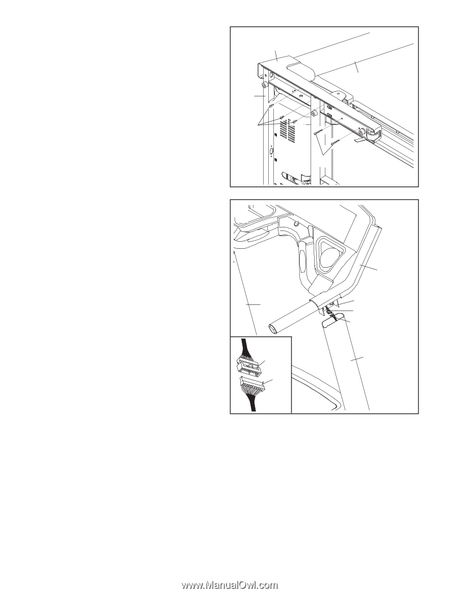
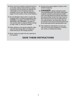
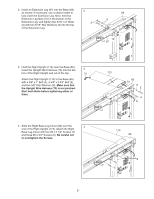
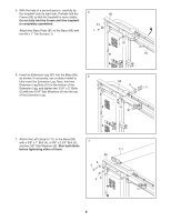
8. Slide the Left Base Leg Cover (82) over the end of the Left Upright (111). Attach the Left Base Leg Cover with three #8 x 3/4" Screws (6) and two #8 x 2 1/4" Screws (7). Be careful not to overtighten the Screws. With the help of a second person, carefully tip the treadmill down so that the Base (85) is flat on the floor. 8 82 85 6 111 7 9. With the help of a second person, hold the console assembly near the Left Upright (111) and 9 the Right Upright (113). Connect the Upright Wire Harness (73) to the Console Wire (119). See the inset drawing. The connectors should slide together easily and snap into place; if they do not, turn one connector and try again. IF THE CONNECTORS ARE NOT CONNECTED PROPERLY, THE CONSOLE MAY BE DAMAGED WHEN YOU TURN ON THE POWER. Then, insert the connectors and the excess wire into the Right Upright (113). Insert the front ends of the brackets on the console assembly into the Right Upright (113) and the Left Upright (111). Then, insert the rest of the brackets into the Uprights. Make sure that the Wire Harnesses (73, 119) are not pinched. 111 119 73 Console Assembly Front of Bracket 119 73 113 9
-
 1
1 -
2
-
3
-
 4
4 -
 5
5 -
 6
6 -
 7
7 -
 8
8 -
 9
9 -
 10
10 -
 11
11 -
 12
12 -
 13
13 -
 14
14 -
15
-
16
-
17
-
18
-
19
-
20
-
21
-
22
-
23
-
24
-
25
-
26
-
27
-
28
-
29
-
30
-
31
-
32
 |
 |