Ricoh AC205 Service Manual - Page 159
SCANNING UNIT, LASER SCANNING UNIT (LSU), CCD Module Specifications
 |
View all Ricoh AC205 manuals
Add to My Manuals
Save this manual to your list of manuals |
Page 159 highlights
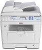
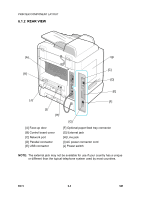
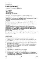
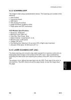
SYSTEM LAYOUT 6.2.5 SCANNING UNIT The image is read using a photosensitive sensor. The scanning unit consists of the following: • CCD module • Connection board • ADF board • AFE (Analog Front End) • Image Processor (located in CPU) • Platen glass and ADF mechanism CCD Module Specifications: • Resolution: 600dpi/A4 • Maximum scan width: 8.5" • Color filter: Red, Green, Blue • Output channel: 3 channels (R, G, B) • Effective pixel: 5,400 pixels • Voltage: 24V & 5V • Pre-heating time: Maximum 30 seconds (70% of light output reached) • Life span of the lamp: 30,000 hours (25° C) 6.2.6 LASER SCANNING UNIT (LSU) The laser-scanning unit converts video data received from machine control into an electrostatic latent image on the surface of the OPC drum. This is achieved by controlling the laser beam and exposing the surface of the OPC drum to the laser light. The polygon mirror reflects the laser light onto the OPC. Each side of the mirror is one scan line. The OPC drum turns as the paper feeds, to scan the image down the page. Detailed Descriptions SM 6-5 B273
-
 1
1 -
2
-
3
-
4
-
5
-
6
-
7
-
8
-
9
-
10
-
11
-
12
-
13
-
14
-
15
-
16
-
17
-
18
-
19
-
20
-
21
-
22
-
23
-
24
-
25
-
26
-
27
-
28
-
29
-
30
-
31
-
32
-
33
-
34
-
35
-
36
-
37
-
38
-
39
-
40
-
41
-
42
-
43
-
44
-
45
-
46
-
47
-
48
-
49
-
50
-
51
-
52
-
53
-
54
-
55
-
56
-
57
-
58
-
59
-
60
-
61
-
62
-
63
-
64
-
65
-
66
-
67
-
68
-
69
-
70
-
71
-
72
-
73
-
74
-
75
-
76
-
77
-
78
-
79
-
80
-
81
-
82
-
83
-
84
-
85
-
86
-
87
-
88
-
89
-
90
-
91
-
92
-
93
-
94
-
95
-
96
-
97
-
98
-
99
-
100
-
101
-
102
-
103
-
104
-
105
-
106
-
107
-
108
-
109
-
110
-
111
-
112
-
113
-
114
-
115
-
116
-
117
-
118
-
119
-
120
-
121
-
122
-
123
-
124
-
125
-
126
-
127
-
128
-
129
-
130
-
131
-
132
-
133
-
134
-
135
-
136
-
137
-
138
-
139
-
140
-
141
-
142
-
143
-
144
-
145
-
146
-
147
-
148
-
149
-
150
-
151
-
152
-
153
-
 154
154 -
 155
155 -
 156
156 -
 157
157 -
 158
158 -
 159
159 -
 160
160 -
 161
161 -
 162
162 -
 163
163 -
 164
164 -
165
-
166
-
167
-
168
-
169
-
170
-
171
-
172
-
173
-
174
-
175
-
176
-
177
-
178
-
179
-
180
-
181
-
182
-
183
-
184
-
185
-
186
-
187
-
188
 |
 |