Ricoh AC205 Service Manual - Page 172
Drive, Transfer, Fusing
 |
View all Ricoh AC205 manuals
Add to My Manuals
Save this manual to your list of manuals |
Page 172 highlights
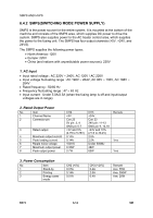
ENGINE 6.5.2 DRIVE The Main Motor drives the following: • Paper feed unit • Developing unit • Fusing unit Software drives the Main Motor and controls the motor acceleration, motor speed, and motor de-celeration. The motor is managed via an A3977 driver IC and is controlled by signals from the CPU. 6.5.3 TRANSFER The charging voltage, developing voltage, and the transfer voltage are controlled by PWM (Pulse Width Modulation). Each output voltage is variable according to the PWM duty cycle. The transfer voltage used when the paper passes the transfer roller is decided by environment recognition. The resistance value of the transfer roller changes due to the surrounding environment in the room or within the set. This change in resistance in turn changes the value of the voltage, due to loading. This voltage is fed back into the set through the A/D converter. Based upon this fed-back value the PWM cycle is changed to maintain the required transfer voltage. 6.5.4 FUSING The temperature of the heat roller's surface is detected from the resistance value of the thermistor. The thermistor resistance is measured with the A/D converter. This allows the CPU to determine the temperature of the heat roller. The AC power is controlled by comparing the target temperature to the value from the thermistor. An error appears if the value from the thermistor is out of the control range during the fusing process. The table below shows the error conditions. Error Open heat error Low heat error Over heat error Description The temperature remains lower than 68° C for more than 25 seconds during warm-up. Standby: The temperature remains lower than 100° C for more than 25 seconds. Printing: 1. The temperature remains lower than 145° C for more than 5 seconds for 2 consecutive pages 2. The temperature remains 40° C lower than the fixed fusing temperature for more than 4 seconds, for 3 consecutive pages. The temperature remains higher than 220° C for more than 3 seconds. B273 6-18 SM
-
 1
1 -
2
-
3
-
4
-
5
-
6
-
7
-
8
-
9
-
10
-
11
-
12
-
13
-
14
-
15
-
16
-
17
-
18
-
19
-
20
-
21
-
22
-
23
-
24
-
25
-
26
-
27
-
28
-
29
-
30
-
31
-
32
-
33
-
34
-
35
-
36
-
37
-
38
-
39
-
40
-
41
-
42
-
43
-
44
-
45
-
46
-
47
-
48
-
49
-
50
-
51
-
52
-
53
-
54
-
55
-
56
-
57
-
58
-
59
-
60
-
61
-
62
-
63
-
64
-
65
-
66
-
67
-
68
-
69
-
70
-
71
-
72
-
73
-
74
-
75
-
76
-
77
-
78
-
79
-
80
-
81
-
82
-
83
-
84
-
85
-
86
-
87
-
88
-
89
-
90
-
91
-
92
-
93
-
94
-
95
-
96
-
97
-
98
-
99
-
100
-
101
-
102
-
103
-
104
-
105
-
106
-
107
-
108
-
109
-
110
-
111
-
112
-
113
-
114
-
115
-
116
-
117
-
118
-
119
-
120
-
121
-
122
-
123
-
124
-
125
-
126
-
127
-
128
-
129
-
130
-
131
-
132
-
133
-
134
-
135
-
136
-
137
-
138
-
139
-
140
-
141
-
142
-
143
-
144
-
145
-
146
-
147
-
148
-
149
-
150
-
151
-
152
-
153
-
154
-
155
-
156
-
157
-
158
-
159
-
160
-
161
-
162
-
163
-
164
-
165
-
166
-
 167
167 -
 168
168 -
 169
169 -
 170
170 -
 171
171 -
 172
172 -
 173
173 -
 174
174 -
 175
175 -
 176
176 -
 177
177 -
178
-
179
-
180
-
181
-
182
-
183
-
184
-
185
-
186
-
187
-
188
 |
 |