Ridgid BS1400 Owners Manual - Page 19
Mounting The Switch Box, Mounting The Dust Chute, Mounting The Table Trunnion Support, To Band Saw
 |
View all Ridgid BS1400 manuals
Add to My Manuals
Save this manual to your list of manuals |
Page 19 highlights
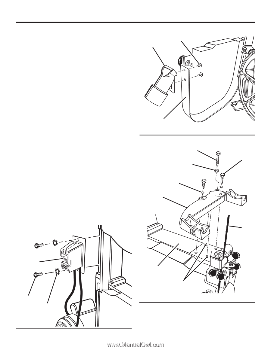
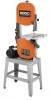
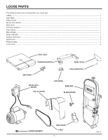
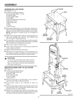
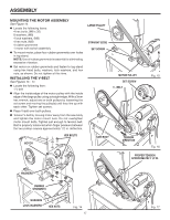
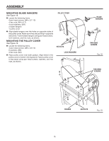
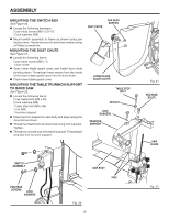
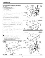
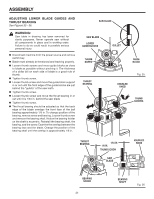
ASSEMBLY MOUNTING THE SWITCH BOX See Figure 20. n Locate the following hardware: 2 pan head screws (M5 x 0.8-12) 2 lock washers (M5) n Mount switch assembly to frame as shown using pan head screws. Thread screws into band saw chassis using a Phillips screwdriver. MOUNTING THE DUST CHUTE See Figure 21. n Locate the following items: 2 pan head screws (M6 x 1) 1 dust chute n Open lower blade guard cover and install dust chute pointing down. Thread pan head screws from the inside of the lower blade guard cover into the dust chute. n Close lower blade guard cover. MOUNTING THE TABLE TRUNNION SUPPORT TO BAND SAW See Figure 22. n Locate the following items: 2 hex head bolts (M8 x 35) 2 lock washers (M8) 1 table stop bolt (M8 x 80) 1 nut (M8) 1 trunnion support n Place trunnion support on saw body and align using pins mounted as shown. n Thread hex head bolts into band saw using lock washers. Tighten. n Thread hex nut half way onto table stop bolt. Thread table stop bolt into trunnion support. DUST CHUTE PAN HEAD SCREWS LOWER BLADE GUARD COVER TABLE STOP BOLT HEX NUT LOCK WASHERS TRUNNION SUPPORT SWITCH ASSEMBLY ON P I U L L P U OFF S H PAN HEAD SCREWS LOCK WASHERS L PUL SAW BODY PINS LL Fig. 20 19 PU Fig. 21 HEX HEAD BOLTS SAW BLADE Fig. 22
-
 1
1 -
2
-
3
-
4
-
5
-
6
-
7
-
8
-
9
-
10
-
11
-
12
-
13
-
 14
14 -
 15
15 -
 16
16 -
 17
17 -
 18
18 -
 19
19 -
 20
20 -
 21
21 -
 22
22 -
 23
23 -
 24
24 -
25
-
26
-
27
-
28
-
29
-
30
-
31
-
32
-
33
-
34
-
35
-
36
 |
 |