Ridgid BS1400 Owners Manual - Page 24
Adjusting Lower Blade Guides And, Thrust Bearing, Warning
 |
View all Ridgid BS1400 manuals
Add to My Manuals
Save this manual to your list of manuals |
Page 24 highlights
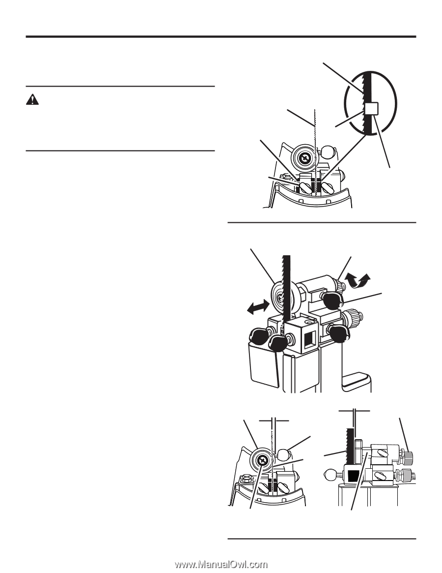
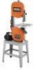
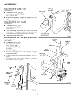
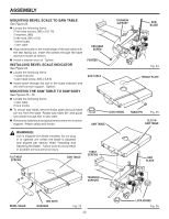
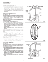
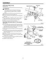
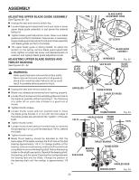
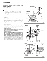
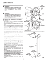
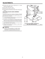
ASSEMBLY ADJUSTING LOWER BLADE GUIDES AND THRUST BEARING See Figures 35 - 36. WARNING: Saw table in drawing has been removed for clarity purposes. Never operate saw without all components in place and in working order. Failure to do so could result in possible serious personal injury. n Disconnect machine from the power source and remove switch key. n Blade must already be tensioned and tracking properly. n Loosen thumb screws and move guide blocks as close to blade as possible without pinching it. The thickness of a dollar bill on each side of blade is a good rule of thumb. n Tighten thumb screw. n Loosen thumb screw and move the guide block support in or out until the front edge of the guide blocks are just behind the "gullets" of the saw teeth. n Tighten thumb screw. n Loosen thumb screw and move the thrust bearing in or out until it is 1/64 in. behind the saw blade n Tighten thumb screw. n The thrust bearing should be adjusted so that the back edge of the blade overlaps the front face of the ball bearing approximately 1/8 in. To change position of the bearing, remove screw and bearing. Loosen thumb screw and remove the bearing shaft. Notice the bearing holder on the shaft is eccentric. Reinstall the bearing shaft, the bearing, and the screw. Examine the overlap between the bearing face and the blade. Change the position of the bearing shaft until the overlap is approximately 1/8 in. SAW BLADE SAW BLADE LOWER GUIDE BLOCKS THUMB SCREW THRUST BEARING GULLET GUIDE BLOCK KNURLED KNOB Fig. 35 THUMB SCREWS THRUST BEARING 1/64 IN. 1/8 IN. THUMB SCREW SAW BLADE KNURLED KNOB BEARING SCREW 24 BEARING SHAFT Fig. 36
-
 1
1 -
2
-
3
-
4
-
5
-
6
-
7
-
8
-
9
-
10
-
11
-
12
-
13
-
14
-
15
-
16
-
17
-
18
-
 19
19 -
 20
20 -
 21
21 -
 22
22 -
 23
23 -
 24
24 -
 25
25 -
 26
26 -
 27
27 -
 28
28 -
 29
29 -
30
-
31
-
32
-
33
-
34
-
35
-
36
 |
 |