Ridgid BS1400 Owners Manual - Page 22
Lassembly
 |
View all Ridgid BS1400 manuals
Add to My Manuals
Save this manual to your list of manuals |
Page 22 highlights
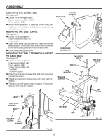
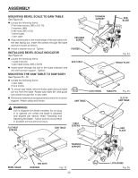
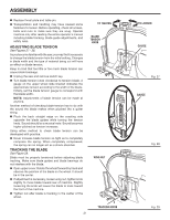
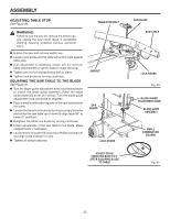
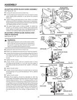
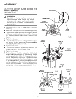
ASSEMBLY ADJUSTING TABLE STOP See Figure 30. WARNING: Failure to turn the saw off, remove the switch key, and unplug the saw could result in accidental starting causing possible serious personal injury. n Unplug the saw and remove switch key. n Loosen lock knobs and tilt table left until it rests against table stop. n If an adjustment is necessary, loosen jam nut and turn table stop bolt left or right to raise or lower the stop. n Tighten jam nut to hold table stop bolt in place. n Tighten lock knobs by turning clockwise. SQUARING THE SAW TABLE TO THE BLADE See Figure 31. n Turn the blade guide adjustment knob counterclockwise to unlock the blade guide assembly. Raise the blade guide assembly as far as it will go. Turn the blade guide adjustment knob clockwise to retighten. n Place a small combination square on the saw table beside the blade. n Loosen the table lock knobs by turning counterclockwise and rotate the saw table up or down to align table 90° to blade (0° position). n Retighten the table lock knobs by turning clockwise. n Check squareness of the saw table to the blade. Make readjustments if necessary. n Loosen screw on scale indicator with a Phillips screwdriver and align scale indicator to zero. n Tighten all screws securely. TABLE STOP BOLT JAM NUT PUL SAW ON P I U L L P U S OFF H O BLADE 10° 0° 15° 30° 4 LOCK KNOBS ADJUST SCALE INDICATOR BACK TO 0° AFTER SQUARING BLADE TO TABLE L L SAW BLADE SAW TABLE 45° 30° 10° 0° 15° PUL LOCK KNOBS Fig. 30 BLADE GUARD ADJUSTMENT KNOB BLADE GUIDE ASSEMBLY SMALL COMBINATION SQUARE 10° 0° 15° 30° 4 Fig. 31 22
-
 1
1 -
2
-
3
-
4
-
5
-
6
-
7
-
8
-
9
-
10
-
11
-
12
-
13
-
14
-
15
-
16
-
 17
17 -
 18
18 -
 19
19 -
 20
20 -
 21
21 -
 22
22 -
 23
23 -
 24
24 -
 25
25 -
 26
26 -
 27
27 -
28
-
29
-
30
-
31
-
32
-
33
-
34
-
35
-
36
 |
 |
