Ridgid BS1400 Owners Manual - Page 9
Changing Motor Voltage, Warning - band saw blades
 |
View all Ridgid BS1400 manuals
Add to My Manuals
Save this manual to your list of manuals |
Page 9 highlights
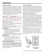
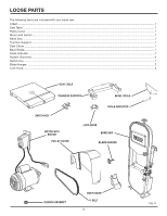
ELECTRICAL CHANGING MOTOR VOLTAGE See Figures 2 - 5. GROUNDING PIN WARNING: Electric shock can kill. To reduce the risk of serious personal injury, never connect plug to power source until all assembly steps are completed. NOTE: The band saw is prewired at the factory for 120 volts, 60 Hz. Use the following procedures to change motor voltage from 120 volts to 240 volts. n Unplug the saw. n Located on the side of the motor is the junction box. Remove the Phillips screw at the back of the junction box then lift off the cover. n Remove and discard the electrical tape from the wire connectors. Remove wire connectors. n Reconnect the leads. n Reinstall the wire connectors and wrap each wire with two layers of new UL listed electrical tape. n Recheck your wiring with the wiring diagrams. n Reinstall the junction box cover using the Phillips screw. n Cut off the 120 volt power cord plug and replace it with a 3-prong 240 volt, 15 amp. UL listed plug. n Connect the power cord white and black leads, respectively, to the "hot" plug blade terminals. Connect the power cord green grounding wire to the plug ground prong terminal. n Plug your table saw into a 220-240 volt, 15 amp., 3-prong receptacle. Make certain the receptacle is connected to a 240 volt, AC power supply through a 240 volt branch circuit having at least a 15 amp capacity and protected by a 15 amp time-delay fuse or circuit breaker. COVER OF GROUNDED OUTLET BOX FOR USE WITH 220-240 VOLT Fig. 3 MOTOR JUNCTION BOX POWER CORD GREEN GROUND WHITE NO. 2 POWER CORD BLACK POWER CORD BLACK WHITE NO. 1 WIRE NUT POWER CORD WHITE WIRE NUT WHITE NO. 4 WHITE NO. 3 WIRE NUT FOR USE WITH 220-240 VOLT Fig. 4 MOTOR JUNCTION BOX POWER CORD BLACK POWER CORD BLACK WHITE NO. 1 WIRE NUT MOTOR JUNCTION BOX POWER CORD GREEN GROUND WHITE NO. 3 POWER CORD WHITE WHITE NO. 4 WHITE NO. 2 FOR USE WITH 110-120 VOLT WIRE NUT Fig. 2 MOTOR JUNCTION BOX COVER 9 POWER CORD MOTOR JUNCTION BOX SCREW Fig. 5
-
 1
1 -
2
-
3
-
 4
4 -
 5
5 -
 6
6 -
 7
7 -
 8
8 -
 9
9 -
 10
10 -
 11
11 -
 12
12 -
 13
13 -
 14
14 -
15
-
16
-
17
-
18
-
19
-
20
-
21
-
22
-
23
-
24
-
25
-
26
-
27
-
28
-
29
-
30
-
31
-
32
-
33
-
34
-
35
-
36
 |
 |
