Ridgid R3400 Owners Manual - Page 10
Assembly - parts
 |
View all Ridgid R3400 manuals
Add to My Manuals
Save this manual to your list of manuals |
Page 10 highlights
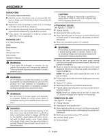
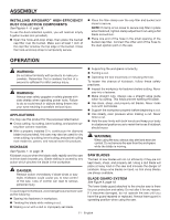
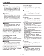
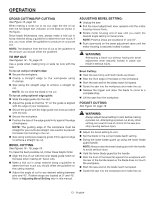
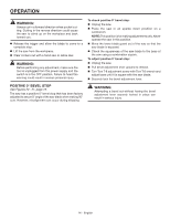
ASSEMBLY UNPACKING This product requires assembly. Carefully remove the product and any accessories from the box. Make sure that all items listed in the packing list are included. Inspect the product carefully to make sure no breakage or damage occurred during shipping. Do not discard the packing material until you have carefully inspected and satisfactorily operated the product. If any parts are damaged or missing, please call 1-866-539-1710 for assistance. PACKING LIST 5 in. Fiber Cement Saw Blade Blade Wrench Hose Bucket Cap Filter Filter Clamp Operator's Manual WARNING: If any parts are damaged or missing, do not operate this product until the parts are replaced. Failure to heed this warning could result in serious personal injury. WARNING: Do not attempt to modify this product or create accessories not recommended for use with this product. Any such alteration or modification is misuse and could result in a hazardous condition leading to possible serious personal injury. WARNING: Do not connect to power supply until assembly is complete. Failure to comply could result in accidental starting and possible serious personal injury. WARNING: 5 in. blade is the maximum blade capacity of the saw. Also, never use a blade that is too thick to allow outer blade washer to engage with the flat on the spindle. Larger blades will come in contact with the blade guides, while thicker blades will prevent blade screw from securing blade on spindle. Either of these situations could result in a serious accident. CAUTION: To prevent damage to the spindle or spindle lock, always allow motor to come to a complete stop before engaging spindle lock. ATTACHING BLADE See Figures 2 - 3, page 17. Unplug the saw. Depress and hold spindle lock. Remove blade screw by turning it counterclockwise with the blade wrench, while keeping the spindle lock button depressed. Remove outer blade washer ("D" washer). WARNING: If inner flange bushing has been removed, replace it before placing blade on spindle. Failure to do so will prevent blade from tightening properly and could result in serious personal injury. Retract the lower guard into the upper guard, making sure the lower guard spring works properly, allowing the guard to move freely. Check to see that the saw teeth and arrow on the saw blade and the arrow on the lower guard are pointing in the same direction. NOTE: The saw teeth point upward at the front of the saw as shown. Fit the saw blade inside the lower blade guard and onto the spindle. Replace "D" washer. Depress spindle lock and replace blade screw. Tighten blade screw securely by turning it clockwise with the blade wrench. NOTE: Never use a blade that is too thick to allow the "D" washer to engage with the flats on the spindle. REMOVING BLADE See Figure 2 - 3, page 17. Unplug the saw. Depress and hold spindle lock. Remove blade screw by turning it counterclockwise with the provided blade wrench, while keeping the spindle lock depressed. Remove outer blade washer ("D" washer). Lift lower blade guard. Remove blade. 10 - English
-
 1
1 -
2
-
3
-
4
-
 5
5 -
 6
6 -
 7
7 -
 8
8 -
 9
9 -
 10
10 -
 11
11 -
 12
12 -
 13
13 -
 14
14 -
 15
15 -
16
-
17
-
18
-
19
-
20
-
21
-
22
-
23
-
24
-
25
-
26
-
27
-
28
-
29
-
30
-
31
-
32
-
33
-
34
-
35
-
36
-
37
-
38
-
39
-
40
-
41
-
42
-
43
-
44
-
45
-
46
-
47
-
48
 |
 |