Ryobi P423 Operation Manual - Page 7
Features, Assembly
 |
View all Ryobi P423 manuals
Add to My Manuals
Save this manual to your list of manuals |
Page 7 highlights
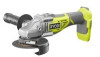
FEATURES PRODUCT SPECIFICATIONS Wheel Capacity 4-1/2 in. Rated Speed 10,600 r/min. (RPM) Spindle Thread 5/8 in. x 11 UNC Wheel Grinding (Type 27) or Cutting (Type 1) ASSEMBLY UNPACKING This product requires assembly. n Carefully remove the tool and any accessories from the box. All items listed in the Includes section must be included at the time of purchase. WARNING: Items in this Assembly section are not assembled to the product by the manufacturer and require customer installation. Use of a product that may have been improperly assembled could result in serious personal injury. n If any parts are damaged or missing, please call 1-800-525-2579 for assistance. WARNING: If any parts are damaged or missing do not operate this product until the parts are replaced. Use of this product with damaged or missing parts could result in serious personal injury. WARNING: Do not attempt to modify this product or create accessories or attachments not recommended for use with this product. Any such alteration or modification is misuse and could result in a hazardous condition leading to possible serious personal injury. INSTALLING/REMOVING WHEEL GUARD See Figures 1 - 3, page 12. To install: Place the guard on the shoulder of the bearing cap by aligning index arrows on guard and bearing cap. Press down on guard until it is fully seated. Depress the lever and rotate guard to the correct position. Refer to Positioning the Wheel Guard. NOTE: Be sure the raised ridge on the guard is seated in the groove on the bearing cap. Install disc flange, grinding or cutting wheel, and clamp nut as described later in this section. Tighten clamp nut securely with the wrench provided. To remove: Remove the disc flange, grinding or cutting wheel, and clamp nut. Depress the lever and rotate guard to align index arrows on guard and bearing cap. Remove the guard. INSTALLING/REMOVING GRINDING WHEEL See Figure 1, page 12. WARNING: Thoroughly inspect a new grinding wheel before you install it on the grinder. • Tap lightly around the wheel using a wooden hammer. • Listen carefully to the resulting sounds. Places with fissures or cracks will result in a different sound. Do not use a wheel containing fissures or cracks. When you install a new grinding wheel, carry out a no load revolution test of approximately one minute with the grinding wheel facing a safe direction, i.e., away from people or objects. Install the wheel guard. Place the disc flange onto the spindle. Make sure the flats on the bottom of the disc flange are engaged with the flats on the spindle. Place the grinding wheel over the spindle. WARNING: Always install a grinding wheel with the depressed center against the disc flange. Failure to do so will cause the grinding wheel to crack when tightening the clamp nut. This could result in serious personal injury because of loose particles breaking off and being thrown from the grinder. Do not overtighten. Thread the clamp nut on the spindle with the flat side of the nut facing up. 7 - English
-
 1
1 -
 2
2 -
 3
3 -
 4
4 -
 5
5 -
 6
6 -
 7
7 -
 8
8 -
 9
9 -
 10
10 -
 11
11 -
 12
12 -
13
-
14
-
15
-
16
-
17
-
18
-
19
-
20
-
21
-
22
-
23
-
24
-
25
-
26
-
27
-
28
-
29
-
30
-
31
-
32
-
33
-
34
-
35
-
36
 |
 |
