Samsung 275C User Manual - Page 23
Setting the DIP Switch
 |
View all Samsung 275C manuals
Add to My Manuals
Save this manual to your list of manuals |
Page 23 highlights
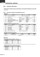
CHAPTER 3 Setting the switches ▌3.1 Setting the DIP Switch Although the factory settings are best for almost all users, if you have special requirements, you can change the DIP Switch. Your printer has two sets of DIP Switches. The functions of the switches are shown in the following table. ▌3.1.1 DIP Switch setting for Epson(ESC/POS) mode • DIP Switch 1 Switch 1-1 1-2 1-3 Function Emulation Selection (*1) Auto cutter 1-4 BUSY condition 1-5 Serial interface selection 1-6 Print NV bit image #1 after cutting 1-7 Near end switch 1-8 Print column ON OFF Refer to the following table Enable Receive buffer full Memory Switch Enable Enable 42/35 Disable Receive buffer full or Offline DIP Switch Disable Disable 40/33 • DIP Switch 2 (RS232C serial interface model) Switch 2-1 2-2 2-3 2-4 2-5 2-6 2-7 2-8 Function Data receive error Hand shaking Word length Parity check Parity selection Baud rate selection (*2) ON Ignore Reserved XON/XOFF 7 bits Enable EVEN OFF Print "?" DTR/DSR 8 bits Disable ODD Refer to the following table • DIP Switch 2 (Parallel interface model) Switch 2-1 2-2~8 Function Auto Line Feed ON Enable Undefined OFF Disable Default OFF OFF OFF OFF OFF OFF OFF Default OFF OFF OFF OFF OFF OFF OFF OFF Default OFF OFF NOTES (*1) Emulation Selection (DSW 1-1 and 1-2) Emulation 1-1 1-2 EPSON OFF OFF STAR OFF ON CITIZEN ON OFF EPSON-KP ON ON - EPSON-KP(EPSON Kitchen Printer mode) : A alarm is generated by printer after auto cutting and in paper end error. (*2) Baud rate selection (Transmission speed) Transmission 2-7 2-8 2400 baud ON ON 4800 baud OFF ON 9600 baud OFF OFF 19200 baud ON OFF 3-1
-
 1
1 -
2
-
3
-
4
-
5
-
6
-
7
-
8
-
9
-
10
-
11
-
12
-
13
-
14
-
15
-
16
-
17
-
 18
18 -
 19
19 -
 20
20 -
 21
21 -
 22
22 -
 23
23 -
 24
24 -
 25
25 -
 26
26 -
 27
27 -
 28
28 -
29
-
30
-
31
-
32
-
33
-
34
-
35
-
36
-
37
-
38
-
39
-
40
-
41
-
42
-
43
-
44
-
45
-
46
-
47
-
48
-
49
-
50
-
51
-
52
-
53
-
54
-
55
-
56
-
57
-
58
-
59
-
60
-
61
-
62
-
63
-
64
-
65
-
66
-
67
-
68
-
69
-
70
-
71
-
72
-
73
-
74
-
75
-
76
-
77
-
78
-
79
-
80
-
81
-
82
-
83
-
84
-
85
-
86
-
87
-
88
-
89
-
90
-
91
-
92
-
93
-
94
-
95
-
96
-
97
-
98
-
99
-
100
 |
 |
