Samsung HT-C6600 User Manual (user Manual) (ver.1.0) (English) - Page 17
Rear Panel, Connect your TV's Video Input jack VIDEO IN to the VIDEO OUT - home theater
 |
UPC - 036725617384
View all Samsung HT-C6600 manuals
Add to My Manuals
Save this manual to your list of manuals |
Page 17 highlights
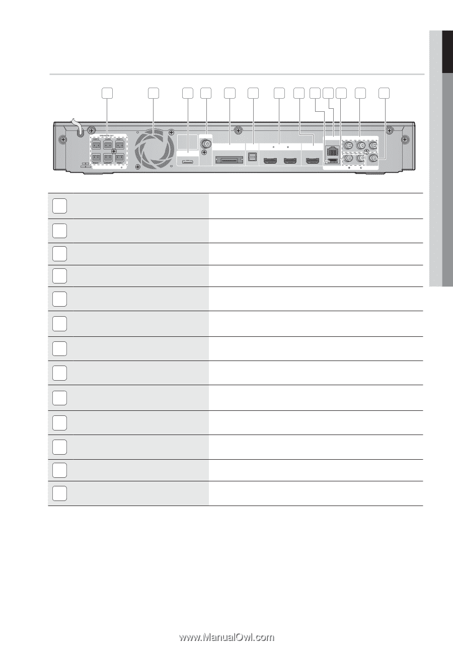
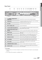
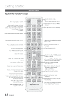
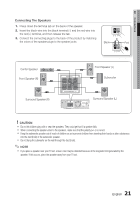
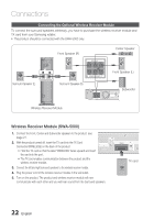
01 Getting Started Rear Panel 1 2 3 4 5 6 7 8 9 10 11 12 13 SPEAKER IMPEDANCE : 3 FM ANT iPod WIRELESS DIGITAL AUDIO IN OPTICAL HDMI IN LAN HDMI OUT COMPONENT OUT WIRELESS LAN AUX IN VIDEO OUT 1 5.1 CHANNEL SPEAKER OUTPUT CONNECTORS 2 COOLING FAN 3 iPod JACK Connect the front, center, surround, subwoofer speakers. The cooling fan supplies cool air to the product to prevent overheating and always revolves when the power is on. Connect the iPod dock connector here. 4 FM 75— COAXIAL JACK 5 TX CARD CONNECTION (WIRELESS) 6 EXTERNAL DIGITAL OPTICAL IN JACKS (OPTICAL) 7 HDMI IN JACKS 8 HDMI OUT JACK 9 WIRELESS LAN JACK 10 LAN TERMINAL 11 AUX IN JACKS 12 COMPONENT VIDEO OUT JACKS 13 VIDEO OUT JACK Connect the FM antenna. The TX card enables communication between the product and the optional wireless receiver module. Use this to connect external equipment capable of digital output. Receives digital video and audio signals simultaneously using an HDMI cable. Using an HDMI cable, connect this HDMI output terminal to the HDMI input terminal on your TV for the best quality picture. Can be used for network based services (see pages 59~64), BD-LIVE and software upgrade with a wireless LAN adapter. Can be used for network based services (see pages 59~64), BD-LIVE and software upgrade under the network connection. Connect to the 2CH analog output of an external device (such as a VCR) Connect a TV with Component video inputs to these jacks. Connect your TV's Video Input jack (VIDEO IN) to the VIDEO OUT Jack on this product. ! CAUTION Provide a minimum of 4 inches of clearance on all sides of the the home theater to ensure adequate ventilation. Do not obstruct the cooling fan or ventilation holes. 17 English
-
 1
1 -
2
-
3
-
4
-
5
-
6
-
7
-
8
-
9
-
10
-
11
-
 12
12 -
 13
13 -
 14
14 -
 15
15 -
 16
16 -
 17
17 -
 18
18 -
 19
19 -
 20
20 -
 21
21 -
 22
22 -
23
-
24
-
25
-
26
-
27
-
28
-
29
-
30
-
31
-
32
-
33
-
34
-
35
-
36
-
37
-
38
-
39
-
40
-
41
-
42
-
43
-
44
-
45
-
46
-
47
-
48
-
49
-
50
-
51
-
52
-
53
-
54
-
55
-
56
-
57
-
58
-
59
-
60
-
61
-
62
-
63
-
64
-
65
-
66
-
67
-
68
-
69
-
70
-
71
-
72
-
73
 |
 |