Sanyo EF60 Instruction Manual, PLC-EF60 - Page 21
Connection Terminals, Interface Board Slots, Notes On Ordering or Using Optional Interface Boards
 |
View all Sanyo EF60 manuals
Add to My Manuals
Save this manual to your list of manuals |
Page 21 highlights
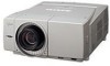
Installation Connection Terminals Terminals to connect AC power cord and other equipment are located in the front part of the projector for easy setup. The terminal area is masked with the front cover to protect them from dust and others, and hide messy cable connections. Remove and replace the front cover following the procedure below: Pushing the button A on right side of the front cover, pull the part forward to remove the front cover. To replace the front cover onto the projector, insert back the left part of the cover into the projector and then push the entire cover back the projector. Make sure the front cover is locked with the button A and fit on the projector. Pull this part forward with pushing button A. Caution Do not push hard or give a strong shock to the cover. It may cause damage to it. Interface Board Slots The projector's front terminal area has two replaceable Interface board slots. The projector's functions can be extended by installing the optional interface boards into the terminal slots. A vacant slot (Input 5) is provided in your purchasing the projector. Install or replace the optional interface boards as follows: Remove 2 screws from an interface board installed in the projector. Pull out the interface board by holding its handles and remove it. Then, insert another board along with the guides inside the slot to fit the socket into the inside plug. Tighten screws to secure the board. ✔Note: When installing or removing the interface board, disconnect the AC power cord from the AC outlet before doing it. ✔Notes On Ordering or Using Optional Interface Boards: When ordering or using the Optional Interface Boards, contact your sales dealer and tell the Model no. of your desired board (p75) and Option Control No. shown in the Information menu. (p31and 61) Terminals Socket Terminal board Screws Option Control No. Installation Front cover A See Option Control No. in the Information menu to order any optional interface board. 21
-
 1
1 -
2
-
3
-
4
-
5
-
6
-
7
-
8
-
9
-
10
-
11
-
12
-
13
-
14
-
15
-
 16
16 -
 17
17 -
 18
18 -
 19
19 -
 20
20 -
 21
21 -
 22
22 -
 23
23 -
 24
24 -
 25
25 -
 26
26 -
27
-
28
-
29
-
30
-
31
-
32
-
33
-
34
-
35
-
36
-
37
-
38
-
39
-
40
-
41
-
42
-
43
-
44
-
45
-
46
-
47
-
48
-
49
-
50
-
51
-
52
-
53
-
54
-
55
-
56
-
57
-
58
-
59
-
60
-
61
-
62
-
63
-
64
-
65
-
66
-
67
-
68
-
69
-
70
-
71
-
72
-
73
-
74
-
75
-
76
-
77
-
78
-
79
-
80
-
81
-
82
-
83
-
84
 |
 |
