Sanyo mpr-214f Instruction Manual - Page 29
Installation of recorder MTR-G3504
 |
View all Sanyo mpr-214f manuals
Add to My Manuals
Save this manual to your list of manuals |
Page 29 highlights
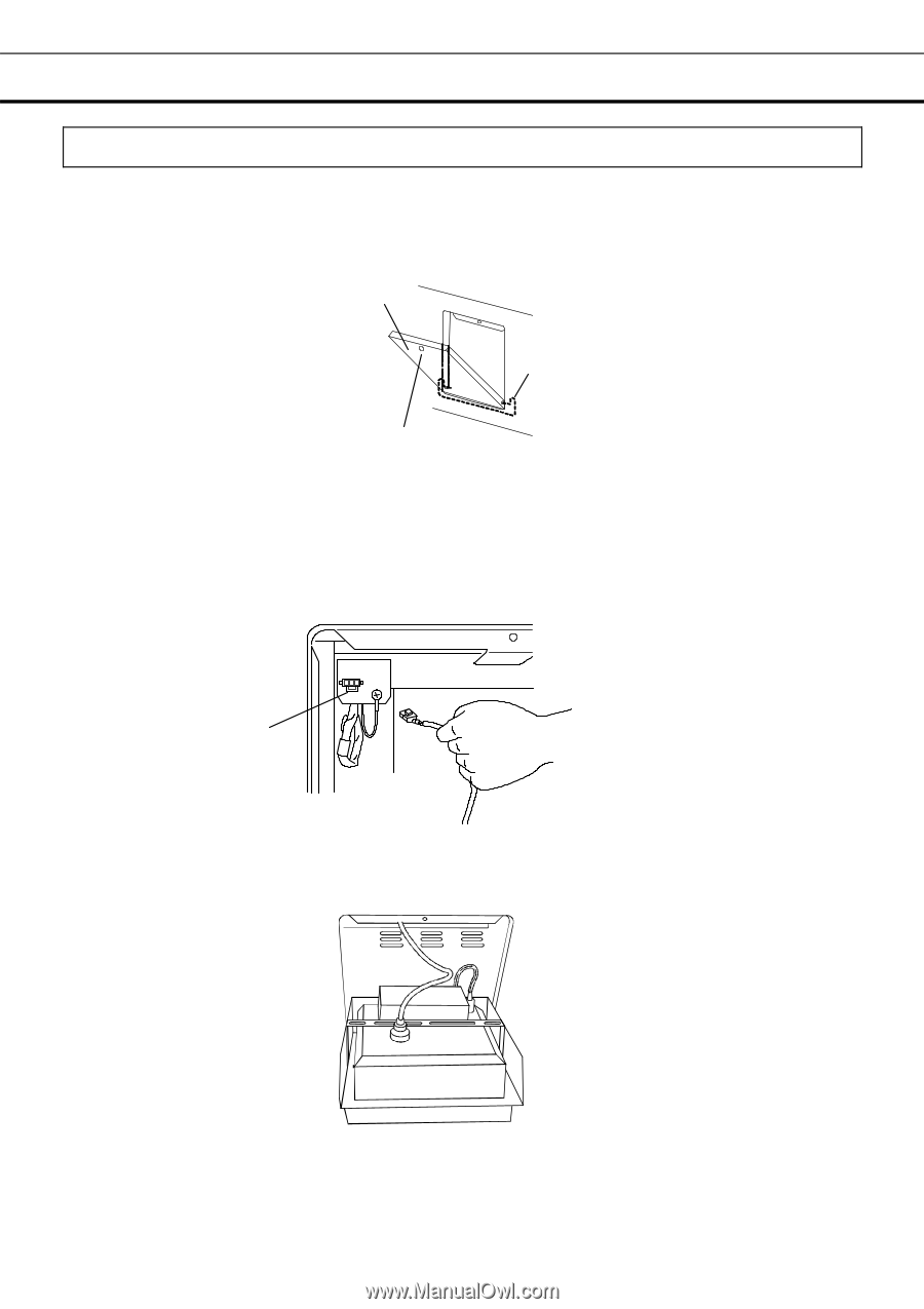
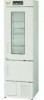
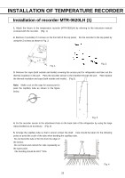
INSTALLATION OF TEMPERATURE RECORDER Installation of recorder MTR-G3504 1. Remove a cap for the fixing screw on the panel cover for mounting space of temperature recorder. Remove the fixing screw and open the panel cover. Remove the panel cover by pushing the shaft on both sides outward. (Fig. 10) Cover panel Fixing screw Shaft Fig. 15 2. Attach the temperature recorder (MTR-G3504) to the recorder fixture (MPR-S7: optional component) by referring to the instruction manual enclosed with the recorder fixture. (Fig. 11) 3. Remove the connector cover on the unit by pushing the lock under the cover. Connect the power supply connector of the recorder with the connector on the unit. (Fig. 16) Lock Fig. 16 4. Remove the cap on the port for taking out the recorder sensor and take out the recorder sensor. Then set the recorder fitting to the space of temperature recorder. (Fig. 17) Fig. 17 28
-
 1
1 -
2
-
3
-
4
-
5
-
6
-
7
-
8
-
9
-
10
-
11
-
12
-
13
-
14
-
15
-
16
-
17
-
18
-
19
-
20
-
21
-
22
-
23
-
 24
24 -
 25
25 -
 26
26 -
 27
27 -
 28
28 -
 29
29 -
 30
30 -
 31
31 -
 32
32 -
 33
33 -
 34
34 -
35
 |
 |