Seagate ST32430N Product Manual - Page 52
Contacts 20-14 AWG
 |
View all Seagate ST32430N manuals
Add to My Manuals
Save this manual to your list of manuals |
Page 52 highlights
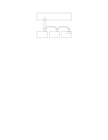
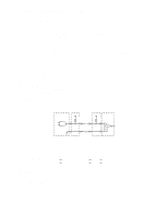
44 Product Manual - Hawk 2LP Family SCSI-2 (Volume 1), Rev. A 11.6.1 DC cable and connector The drive receives DC power through a 4 pin connector (see Figure 11.6-1 for pin assignment) mounted at the rear of the main PCB. Recommended part numbers of the mating connector are listed below, but equivalent parts may be used (see Table 11.6-1). 11.6.2 Table 11.6.1-1. Mating connector parts Type of Cable Connector Contacts (20-14 AWG) 14 AWG MP 1-480424-0 AMP 60619-4 (Loose Piece) AMP 61117-4 (Strip) Physical characteristics This section defines the connectors, cables, signals, terminators and bus timing needed to implement SCSI. 11.6.2.1 Physical description The drives may be daisy-chained together or with other compatible SCSI devices using a common cable. Both ends of the cable must be terminated. The "N" model drive implements single ended drivers and receivers. The "ND" model drive implements differential drivers and receivers. All signals are common between all SCSI devices. The drive may be daisy-chained only with SCSI devices having the same type drivers and receivers. Devices having single ended interface circuits cannot be on the same daisy-chain with devices having differential interface circuit. A maximum of 8 SCSI devices (including the Host) may be daisy-chained together. The SCSI Devices at both ends of the daisy-chain are to be terminated. Intermediate SCSI devices shall not be terminated (see Figure 11.6.3-2). Remove the terminator enable jumper TE on J2 select header ("N" models), or the external terminators ("ND" models), not the terminator power source selector jumper TP (Figure 10.1-1). 11.6.2.2 Cable requirements The maximum total cable length for use with drives having single ended I/O driver and receiver circuits shall be 6 metres (19.7 ft.) when operating at line data transfer rates of 5 Mbytes/sec or less, and 3 metres (9.85 ft.) when operating at transfer rates greater than 5 Mbytes/sec (FAST SCSI). A stub length of no more than 0.1 metre (0.33 ft.) is allowed off the mainline interconnection with any connected equipment. An ideal impedance match with cable terminators implies a cable characteristic impedance of 132 ohms. Single ended I/O cable pin assignments are shown in Table 11.6.3-1.
-
 1
1 -
2
-
3
-
4
-
5
-
6
-
7
-
8
-
9
-
10
-
11
-
12
-
13
-
14
-
15
-
16
-
17
-
18
-
19
-
20
-
21
-
22
-
23
-
24
-
25
-
26
-
27
-
28
-
29
-
30
-
31
-
32
-
33
-
34
-
35
-
36
-
37
-
38
-
39
-
40
-
41
-
42
-
43
-
44
-
45
-
46
-
 47
47 -
 48
48 -
 49
49 -
 50
50 -
 51
51 -
 52
52 -
 53
53 -
 54
54 -
 55
55 -
 56
56 -
 57
57 -
58
-
59
-
60
-
61
-
62
-
63
-
64
-
65
-
66
-
67
-
68
-
69
-
70
 |
 |
