Seagate ST32430N Product Manual - Page 55
Product Manual - Hawk 2LP Family SCSI-2 Volume 1, Rev. A, Signal, Pin Number, Notes., Caution
 |
View all Seagate ST32430N manuals
Add to My Manuals
Save this manual to your list of manuals |
Page 55 highlights
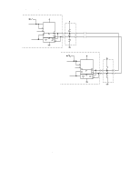
Product Manual - Hawk 2LP Family SCSI-2 (Volume 1), Rev. A 47 SCSI Device Host Adapter/Initiator * * * T * 1 thru 8 SCSI Devices * * Disc Drive or Other SCSI Device * * Disc Drive or Other SCSI Device * T Disc Drive or Other SCSI Device VIEW B - T indicates termination required Total interface cable length must not exceed that specified in paragraph 11.6.2.2. (including host adapter/initiator). * Closed end type connector used. ** Open end type (in-line application) connector used. *** Host need not be on the end of the daisy-chain. Another device can be on the end with the terminator, the host having no terminator. Figure 11.6.3-2. Interface cabling Table 11.6.3-1a. Single ended, 50 pin cable pin assignments (Nonshielded connector) (N models) Signal Pin Number Signal -DB (0) 2 GROUND -DB (1) 4 -ATN -DB (2) 6 GROUND -DB (3) 8 -BSY -DB (4) 10 -ACK -DB (5) 12 -RST -DB (6) 14 -MSG -DB (7) 16 -SEL -DB (P) 18 -C/D GROUND 20 -REQ GROUND 22 -I/O GROUND 24 TERMPWR 26 GROUND 28 Notes. 1. All odd pins except pin 25 are connected to ground. Pin 25 is left open. Pin Number 30 32 34 36 38 40 42 44 46 48 50 Caution Pin 25 must not be connected to ground at the HOST end or the drive end of the cable. If the I/O connector should accidentally be plugged upside down, terminator power on pin 26 will be shorted to ground. 2. The minus sign next to the signals indicates asserted state is the low voltage of the two levels used for logic signals.
-
 1
1 -
2
-
3
-
4
-
5
-
6
-
7
-
8
-
9
-
10
-
11
-
12
-
13
-
14
-
15
-
16
-
17
-
18
-
19
-
20
-
21
-
22
-
23
-
24
-
25
-
26
-
27
-
28
-
29
-
30
-
31
-
32
-
33
-
34
-
35
-
36
-
37
-
38
-
39
-
40
-
41
-
42
-
43
-
44
-
45
-
46
-
47
-
48
-
49
-
 50
50 -
 51
51 -
 52
52 -
 53
53 -
 54
54 -
 55
55 -
 56
56 -
 57
57 -
 58
58 -
 59
59 -
 60
60 -
61
-
62
-
63
-
64
-
65
-
66
-
67
-
68
-
69
-
70
 |
 |
