Seagate ST32430N Product Manual - Page 53
W/O Strain Relief, No Center Key
 |
View all Seagate ST32430N manuals
Add to My Manuals
Save this manual to your list of manuals |
Page 53 highlights
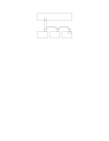
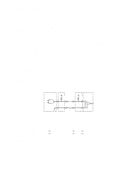
Product Manual - Hawk 2LP Family SCSI-2 (Volume 1), Rev. A 45 11.6.2.3 General cable characteristics In general, cables having the characteristic impedance's given in 11.6.2.2 are not available; however, impedance's that are somewhat lower are satisfactory. A characteristic impedance of 100 ohm ±10% is recommended for unshielded flat or twisted pair ribbon cable. However, most available cables have a somewhat lower characteristic impedance. To minimize discontinuances and signal reflections, cables of different impedance's should not be used in the same bus. Implementations may require trade-offs in shielding effectiveness, cable length, the number of loads, transfer rates, and cost to achieve satisfactory system operation. If shielded and unshielded cables are mixed within the same SCSI bus, the effect of impedance mismatch must be carefully considered. Proper impedance matching is especially important in order to maintain adequate margin at FAST SCSI transfer rates. Only nonshielded cable connectors are applicable. A 50 conductor flat cable or 25 twisted pair cable shall be used. A minimum conductor size of 28 AWG should be used to minimize noise effects. Suggested nonshielded flat cable part numbers are: Flat cable - 35M-3365-50 Twisted pair - Spectra Twist in flat 455-248-50 11.6.3 Mating connector requirements 11.6.3.1 Mating connectors for models N/ND The nonshielded cable connector shall be a 50 conductor connector consisting of two rows of 25 male contacts with adjacent contacts 100 mils apart. Recommended mating flat cable connector part numbers are: Closed end (for cable ends)* 3M-3425-7000 3M-3425-7050 Dupont-66900-290 W/O Strain Relief, No Center Key With Strain Relief, No Center Key With Strain Relief, With Center Key Open end 3M-3425-6000 (In daisy-chain) 3M-3425-6050 Dupont-66900-250 W/O Strain Relief, No Center Key With Strain Relief, No Center Key With Strain Relief, With Center Key *See Figure 11.6.3-2. The drive device connector is a nonshielded 50 conductor connector consisting of two rows of 25 female pins with adjacent pins 100 mils apart. The connector is keyed (see Figure 11.6.3-1). 11.6.3.2 Jumper plug part number for J2 Option select header connector J2 on the PCB (see Figure 10.1-1) uses an unusual type of jumper plug so its part number is given here for reference. Suggested part no. for J2 jumper: Molex 52747-0211 (Seagate P/N 77679052)
-
 1
1 -
2
-
3
-
4
-
5
-
6
-
7
-
8
-
9
-
10
-
11
-
12
-
13
-
14
-
15
-
16
-
17
-
18
-
19
-
20
-
21
-
22
-
23
-
24
-
25
-
26
-
27
-
28
-
29
-
30
-
31
-
32
-
33
-
34
-
35
-
36
-
37
-
38
-
39
-
40
-
41
-
42
-
43
-
44
-
45
-
46
-
47
-
 48
48 -
 49
49 -
 50
50 -
 51
51 -
 52
52 -
 53
53 -
 54
54 -
 55
55 -
 56
56 -
 57
57 -
 58
58 -
59
-
60
-
61
-
62
-
63
-
64
-
65
-
66
-
67
-
68
-
69
-
70
 |
 |
