Seagate ST32430N Product Manual - Page 57
Receiver Characteristics
 |
View all Seagate ST32430N manuals
Add to My Manuals
Save this manual to your list of manuals |
Page 57 highlights
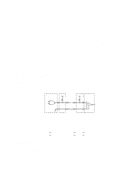
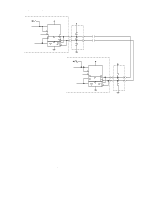
Product Manual - Hawk 2LP Family SCSI-2 (Volume 1), Rev. A 49 11.6.4 Electrical description Model "N" drives use single ended interface signals. These signals must be terminated with 110 ohm active termination circuits at each end of the total cable. On "N" models, the terminators are enabled (or disabled) by installing (or removing) jumper plug TE. See Figure 10.1-1. Single Ended circuits use open collector or three state drivers. See Figure 11.6.4-1 and 11.6-1. The model NC has no provisions for terminators on the drive. The "ND" model drives use differential interface signals and each of these must be terminated at each end of the total cable with 330 ohms to +5 V and 330 ohms to ground with 150 ohms between each differential pair. All I/O circuits are open collector, three state drivers. See Figure 11.6.4-2 for circuit drawing. Differential I/O drives are shipped without terminators. These drives have no provisions for adding terminator sockets on the PCB. On these drives some method of external termination must be provided by the drive user, systems integrator or host equipment manufacturer. 11.6.4.1 Single ended drivers/receivers For "N" models which use single ended drivers and receivers, typical circuits are shown in Figure 11.6.4-1. Terminator circuits (Note [1]) are to be enabled (model N) only when the disc drive is first or last in the daisychain. Transmitter Characteristics Single ended drives use an ANSI SCSI compatible open collector single ended driver. This driver is capable of sinking a current of 48 mA with a low level output voltage of 0.4 volt. Receiver Characteristics Single ended drives use an ANSI SCSI single ended receiver with hysteresis gate or equivalent as a line receiver. Line Driver Transmitter (or transceiver) TP [4] 110 [1] Ohm Flat Cable Pair Line Receiver TP [4] Receiver 110 [1] Ohm [3] [2] [2] [1] Part of active terminator circuits. Non-removable LSI terminators, enabled in the drive (model "N" only) with jumper plug TE when it is first of last in the daisy-chain. Interface signals levels and logical sense at the drive I/O connector are defined as follows: Logic Level Driver Output Receiver Input NEGATED (0) >2.5 V: 2.0 V:
-
 1
1 -
2
-
3
-
4
-
5
-
6
-
7
-
8
-
9
-
10
-
11
-
12
-
13
-
14
-
15
-
16
-
17
-
18
-
19
-
20
-
21
-
22
-
23
-
24
-
25
-
26
-
27
-
28
-
29
-
30
-
31
-
32
-
33
-
34
-
35
-
36
-
37
-
38
-
39
-
40
-
41
-
42
-
43
-
44
-
45
-
46
-
47
-
48
-
49
-
50
-
51
-
 52
52 -
 53
53 -
 54
54 -
 55
55 -
 56
56 -
 57
57 -
 58
58 -
 59
59 -
 60
60 -
 61
61 -
 62
62 -
63
-
64
-
65
-
66
-
67
-
68
-
69
-
70
 |
 |
